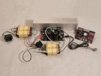
I've identified a great little stereo amp that works well with the
SG4 sinewave generator for use as the output stage and motor drive for AC synchronous or AC induction turntable motors. It is based on a pair of the venerable LM3886 chip amps and contains everything needed to boost the SG4 signal up to a level needed to drive a 6V to 115V (or 230V) transformer. The only additional items needed to make a complete motor drive system is the AC input power transformer, the output transformer, the SG4, a heat sink and a slight modification to the amplifier. A complete motor drive can be constructed for ~$100 plus case.
The amp is available on e-Bay for $15.17 including shipping:
60W LM3886TF Sound Audio Amplifier 2-Channel Digital Power AMP | eBay
The amp will need to be modified to reduce the gain for two reasons:
1. The SG4 output is 5VPP and the amp will go into clipping at ~0.75VPP input.
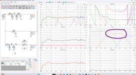
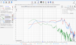
2. With the standard gain, the output waveform becomes quite distorted when connected to the output transformer. With reduced gain, distortion remains very low, even when driving heavy loads and even at 50Hz.
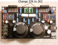
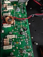
If you do not modify the MK-154 gain, the output waveform will look terrible, especially at 50 or 60Hz.
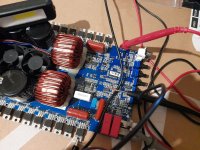
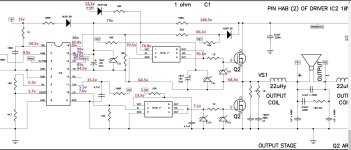
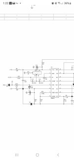
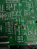
Replace or parallel the two 22K resistors with 2.2K resistors as shown in the attached jpeg (MK-154 Modified.jpeg). With this gain setting, the 5VPP output of the SG4 will drive the output of the transformer to ~125VRMS with very little distortion.
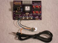
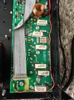
The amp PCB has screw terminals for the AC input, removable connectors for the outputs and both a 3.5mm stereo jack and 3 pin header for the audio inputs.
I've created wiring diagrams for 3 different scenarios:
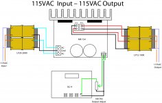
1. 115VAC input and output single phase.
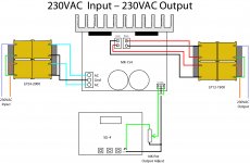
2. 230VAC input and output single phase.
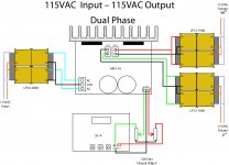
3. 115VAC input and output dual phase.
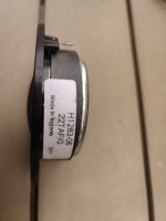
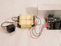
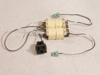
The design uses two low cost split bobbin transformers with dual primaries and dual secondaries. The AC input transformer is a Signal LP24-2000 (48W) and the output transformer is a Signal LP12-1900 (24W). Both are available from Mouser ($24 and $19 respectively).
For 115VAC input or output, the high voltage primary windings are connected in
parallel. For 230VAC input or output, the high voltage primary windings are connected in
series.
Warning: Working with high voltage can be dangerous. Do not attempt to wire these circuits unless you are comfortable and competent to work with high power and high voltage electronics. If wired incorrectly, damage to property and great bodily harm may result.
The wiring diagrams are labeled with the pin numbers on the transformers and are unique to these two parts. If you substitute different transformers you must be aware of the winding polarities of the coils, which are usually indicated with a "DOT".
When connecting windings in parallel, the "dots" must be connected together on one side and the non-dot ends must be connected on the other. When connecting windings in series (for 230VAC input or output), the dot on the lower winding must connect to the non-dot end of the upper winding.
When working with AC line voltages,
ALWAYS use fuses on both the input and output. The AC input transformer in the attached jpegs has an IEC socket with built in fuse holder for connection to the mains voltage; the fuse should be rated for 1A Slo-Blo type. The AC output should also have a 0.5A Slo-Blo fuse in line with the hot lead.
Connect the earth safety ground (third/green wire) from the input connector to all chassis components (and the 3rd terminal on the AC output) to properly ground them.
The MK-154 PCB has detachable connectors on both the L & R outputs. Remove these for easier connection to the output transformer low voltage secondary windings and the transformer will then just plug in for assembly.
For single phase applications, both L & R audio inputs to the MK-154 are connected together and are driven by the 0° output of the SG4. The L & R outputs of the MK-154 are used to drive each winding of the dual low voltage secondary on the output transformer. When wired in phase, they will combine both channels into one output, doubling the current capability.
For dual phase applications, the 0° and 90° outputs of the SG4 drive the L & R audio inputs of the MK-154. Each MK-154 output (L & R) drives its own output transformer with the low voltage secondary windings on each transformer, connected in parallel.
Note that the output connectors on the PCB are mirror images of each other, so the + & - connections are not on the same side of the PCB for each connector. They will be on the same side of each connector that plugs into the PCB.
The MK-154 MUST have an adequate heat sink attached to the two LM-3886 output amps for proper operation. Failure to use a heat sink will result in almost immediate destruction of the amplifier. Use a heat sink with at least 40 square inches (250 cm²) of surface area and at least 2-3 inches deep. The LM3886 chips are in an isolated package so they do not require mica insulators between the chips and the heat sink, however, you will need to use silicone heat sink grease.
If you use the 3.5mm audio input jack to the MK-154, the tip is Right In, Ring is Left In and Sleeve is ground.