Trying to find good options on multi-coloured heat shrink (Europe)

Hey everyone.

I'm trying to restock my heat shrink tubing and I'm wondering where people get their heat shrink from in Europe. I'm looking at farnell and mouser, but any options outside of white, black and red seem to be much, much more expensive than their more common counter part. Am I looking in the wrong place or should I expect to pay anywhere from 3x to 10x the amount on blue/yellow coloured heat shrink?

Thanks in advance for any input 🙂

New poster - Questions about KEF drivers

New poster here though I've been a lurker for yearks.

I ran into a very good deal on both KEF Q800DS and R800DS. I've incorporated some of them in my surround system but I'd like to use the other drivers to make non-dipole speakers, similar to the KEF R8 speakers.

However, after some research I've come to find out that the drivers used in these units vary a bit from the LS50 and Q150s in that the MF/LF driver is 8ohm while the tweeter is 4ohm.

Will I be able to build a crossover to make these work properly? I'd be trying to get 4ohm (nominal) tweeters to work with 8ohm woofers.

DIYer from the UK

Hi there, very much a DIYer, I create lots of different Arduino-type projects, both for myself and acquaintances.

Here are a couple of projects I've incorporated audio into....

1. I call it the HBTY box, and it is installed in a sports bar/restaurant I do all the technical; stuff for. It has Line-In (from the Sky receivers), AUX In (for anything else), Bluetooth connectivity, USB stick (for playing mp3 files, and a special button for playing the owner's preferred "Happy Birthday to You" song from a MicroSD card when someone celebrates with a cake etc.

All controlled by a PT2134 4 into 1 audio processor module, under the watchful eye of an Arduino Nano. Source changes are all faded in and out, so it's a "proper job".


2. In the same venue, the house speaker system is used for the multiple screen sports, but they have recently installed a jukebox. It's a PITA for the bar staff to have to turn down the house system when they allow the jukebox to be played (some sports, especially football matches, take priority). I've built a detection box that can be fed from an unused speaker outlet on the jukebox, which will cause the house sound system to fade to zero as soon as it "hears" the jukebox playing, and fades it up again after a programmable silence period (inter-track delay). Although I should have used logarithmic digital potentiometer ICs, we can get away with linear, because the house system is either fully-on, or fully-off. It being a linear fade is noticeable, but not badly so...

I could go on some more, but that's enough of me boring you all...
  • Like
Reactions: ianbo

For Sale Tube amp OPT

I have a large quantity of the guitar amp specific open frame Push Pull OPT's seen here, still in their original 8 pack boxes from 1990. These are the same transformers seen in my "under 100 WPC" tube amp experiments dating back to the early 2000's. Originally made by Schumaker Electric for ADA Signal Processors for guitar amp duty, they are rated for "80 VA from 82 Hz to 5000 Hz 6600 ohms to 0-4-8-16." They work well at 3300 ohms to 0-2-4-8, which is how I usually run them.

It is pretty hard to make an OPT that only goes to 5KHz, so I have tested them in HiFi applications. They were used in my 300Beast, a zero feedback push pull amp that used 300B tubes. Here they went from 25 Hz to 18.5 KHz at 10 watts with some saturation seen at 28 watts below 30 Hz. They do better when driven with low impedance sweep tubes, and slightly worse in an SPP amp with EL84's that really want an 8000 ohm load. They are a standard size as I have found some end bells from other transformers, that fit.

Stuffing over 100 watts through one for guitar use seems OK, but don't play bass through one beyond about 35 watts. I will sell small quantities to interested builders. for $30 each. They weigh a little over 5 pounds each so shipping isn't cheap and international shipping is probably not viable. Up to 4 transformers will go into a medium flat rate box for delivery in the US for $19

For those that shop hamfests, I have been selling these at the Dayton Hamfest for years, but at a higher price. I will be there again this year, so if you want these at the Hamfest, mention this forum to get them at $30.

Attachments

  • P4020299.JPG
    P4020299.JPG
    536.7 KB · Views: 171
  • P4020301.JPG
    P4020301.JPG
    432.6 KB · Views: 165
  • P4020308.JPG
    P4020308.JPG
    291 KB · Views: 174
  • Like
Reactions: Alfi and gupsta

For Sale Shure TPA-3116 amplifier

Completed PCB only. Just add power through the DC jack and it works. A laptop power supply works fine. Used for a while to power TV speakers. The TPA-3116 was highly regarded for sound quality and it suited my needs fine, but I purchased an amp with trigger capability to pair with my DAC.

$20 shipped. Payment by PayPal. SOLD

Attachments

  • 20240327_142603.jpg
    20240327_142603.jpg
    469.8 KB · Views: 175

Chip amp modification to current drive

I wonder if someone tried to make from a chip amplifier a current amplifier design (inspired by Esa Merilainens - current drive info Website) if that is technically possible.

Maybe it is easier to do that with a chip amp or it is not possible at all. At hand I have some amplifier with TDA7266 soon - which has two times seven watts.

Would like to hear some feedback on this, maybe a modification of an existing mini-amplifier from the far east which could be found easily on ebay.

It would be enough for me to have two times five watts, just in order to hear such an amplifier together with classical fullrange loudspeakers with double cones.

I am only interested in pure current drive, no voltage drive in the bass. As I always build my loudspeakers by myself and never use commercial ones.

Dragan from germany

  • Poll Poll
Bliesma or KEF?

Which?

  • KEF Coax

    Votes: 9 40.9%
  • MTM (Bliesma and Purifi)

    Votes: 11 50.0%
  • Neither

    Votes: 2 9.1%

Like it says on the tin. Doing a redesign of something I'm working on (set of monitors). Was thinking of doing an MTM (4" purifis and a T25B tweeter). However, I may have an opportunity to get my hands on a pair of blade uni-q drivers. If I was going for best noise figures possible, which would be the better pick?

(Disclaimer 1. Yes I am aware that expensive drivers do not make a good speaker. Good design does that. This is just a starting point)
(Disclaimer 2. Both work out to be about the same in cost, so not a factor here)
(Disclaimer 3. This will be used with DSP plate amp)

CD player not responding to open close tray button

Hello all,

I have an Onkyo DX2800 which decided to act up yesterday. The open close button does not work. The symptoms are as follows:

Upon startup, the tray motor is heard to be running. Initially I thought the belt is slipping. I replaced the belt, it did not slip this time, but the tray motor continues to run. The laser eye moves up and down. Nothing happens with or without CD. At this point I shut off the power for fear of burning out the tray motor. On closer inspection, I noticed the tray microswitch does not stop the the tray motor when the switch is activated (tray fully extended, table down; and also when tray is fully inserted, table up). The gears turn the microswitch back to the neutral position, causing the tray motor to run nonstop. I touched the tray motor IC, it is very hot.

The microswitch is the closed type , not the plastic sheath over two ends. I try spraying contact cleaner into it, but no improvement. I did the usual maintenance, oil on spindle bearings, cleaning the lens, lubing the rail, etc. Didn't help.

I then cleaned the door microswitch and replaced a couple of caps (100uf) near the tray motor ICs. Surprisingly, with 3 of the ribbon cables disconnected (2 from laser, 1 from sled motor; the tray motor is connected), the open close buttons works correctly. I connected the 2 laser ribbon cables, and it still works . However , when I connected the sled motor ribbon cables, it is back to the original symptoms (tray motor turns and does not stop, control panel unresponsive). I had initially thought about recapping the Power Supply Unit, as there seem to be some logic error with the startup sequence. However, since it is the spindle and sled motors circuit which keeps tripping the unit up, I tested the sled and spindle motor out of circuit, using a 9v battery. The sled motor works, the spindle did not. Only after turning it a few degrees by hand did it spurt to life and died. That would mean the end of the spindle motor?

I would greatly appreciate any thoughts, thank you very much.

For Sale WW2 Moving Coil Meters - Pairs. UK

FS World War Two NOS moving coil identical meters pairs. These were made circa 1942/43 & carry the war ministry arrow. These are very high quality meters, the chances of finding pairs is low. I've a few to sell but will start with..

1) 3 1/4" (80mm) , 2 1/2" cutout ( 63mm), 1 1/4" (35mm) deep + bolts 1 1/4" (35mm). 2A FSD - 1943.

2) 2 3/16" (55mm), 2 1/8" (53mm) cutout, 1 1/4" (35mm) deep + bolts 3/4" (20mm( 30mA FSD - 1942?

£30 each pair + £3.50 post, UK mainland. Happy to ship overseas.

Andy.

Attachments

  • IMG_3437.JPG
    IMG_3437.JPG
    276.4 KB · Views: 115
  • IMG_3438.JPG
    IMG_3438.JPG
    235.4 KB · Views: 114
  • IMG_3440.JPG
    IMG_3440.JPG
    176 KB · Views: 101
  • IMG_3441.JPG
    IMG_3441.JPG
    273.1 KB · Views: 99
  • IMG_3442.JPG
    IMG_3442.JPG
    269.3 KB · Views: 102
  • IMG_3443.JPG
    IMG_3443.JPG
    264.4 KB · Views: 99
  • IMG_3444.JPG
    IMG_3444.JPG
    216.8 KB · Views: 110

[SALE] Analog Discovery Audio Measurement Extension Board

For sale is one assembled and tested extension boards for Analog Discovery or Analog Discovery 2, which is useful for taking audio measurements (e.g. THD, IMD and so on) while testing (tube) amplifiers. A couple left after I built two for myself. I also put it on eBay but it might be not visible for some countries.

It can be used with the original software, WaveForms, but also with the Audio Analyzer Suite from TheStuffMade:

You can see how it can be used here:
Login to view embedded media https://www.dropbox.com/sh/ecgo4oiw7u9o3e0/AADu20wAB4aP10wQsXyrwCpNa?dl=0

The project description and how to use the board is here:
https://boffin.nl/wp/analog-discovery-audio-board/

NOTE: the actual analog discovery 2 visible on the photos is not for sale and only for the illustrative purposes.

Shipping to the EU/UK or US is no problems. The shipping costs are $8 for EU/UK and $13 for US, as a small package (<100gr) with a tracking number.

Attachments

  • s-l1600-2.jpg
    s-l1600-2.jpg
    351.6 KB · Views: 139
  • s-l1600-3.jpg
    s-l1600-3.jpg
    464.7 KB · Views: 164
  • s-l1600-4.jpg
    s-l1600-4.jpg
    352.8 KB · Views: 147
  • s-l1600.jpg
    s-l1600.jpg
    448.6 KB · Views: 137

Insulated cable standoffs for ground wire

Hey y'all.

I'm looking for an insulated standoff for a wire for a ground scheme for tube amps. The idea is to have a ring ground like structure where multiple connections are made to various single points, these points go to a twisted pair of 20AWG tinned copper wire and then there is one ground point near the input (like what Psionic Audio has suggested in his videos).

I'd like to be able to mount this twisted ground wire around the component board, and obviously not touch the chassis, so I need some sort of stand off that physically raises and holds the wire in place.

Something like this, but much smaller (obviously) and chassis mounted.
s-l1600.jpg

Any idea where I could get this/what it would be called? Thanks in advance!

Good 4" full range for guitar Amp / BT speaker combo?

I've fallen in love with the form factor of "desktop" guitar amps. What I want to kind of recreate is something like the Positive Grid Spark (I won't link in my first post ever for fear of being called a shill/bot lol). It is two 4" FR drivers, 40W total, in a ported box about 14"W x 7"D x8"H, and about 11-12lbs.

I'm looking for some recommendations specifically for the drivers. I'd like to keep driver price under about $80 for the pair.

The design I'm currently planning:
  • separate inputs for BT and guitar (wired). Using the guts of a multiFX pedal to do the amp/cab simulation DSP for the specific guitar Amp sound. (BT circuitry will be clean without Amp/cab DSP).
  • Useage will be about 50/50 guitar Amp vs BT speaker.
  • Planning about 30W per driver, but I'm flexible.
  • Ideal build would be a sealed box but I want to keep very close to the small desktop form / dimensions listed above so may need a port. Hell I'm even open to infinite baffle open back like "real" guitar amps of my youth.

Thoughts?

Hello

Afternoon all.

New member Mike here.

I'm semi-retired and now indulging in a bit of Hi-Fi and PA repair, modification and building. I part own a record shop which generates lots of requests to help get Ho-Fi from the loft working again plus I try to help local musicians with their gear etc.

Looking to read about other people's projects and get a bit of help myself from the learned members on here.

Speak soon!

Telefunken PCC88

A pair new in box and new old stock. Of the same batch, same production year very long ago. One of the best PCC/ECC88 one can find. Current filament type as known. Contrary to what is usually mocked these were actually produced by fairies. German fairies with names like Hildegard that also handrolled perfect paper in oil capacitors. Thus contributing to the Wirtschaftswunder.

You finally have the opportunity to debate the benefits of ring getters and if you have slight OCD you can wonder why one has been opened. I know the answer but won’t tell 😉

Offer by PM. EU only!

Attachments

  • IMG_8021.jpeg
    IMG_8021.jpeg
    858.8 KB · Views: 71
  • IMG_8022.jpeg
    IMG_8022.jpeg
    764.4 KB · Views: 74

For Sale Two high quality low voltage PSUs

1. All in one PSU with 5VA Talema transformer, rectifiers and CRC filter for +/-5V included are two brand new LDOVR TPS7A regs for +/- 5V output. Perfect for DAC 5V supply. Used with Miros DACs
Will throw in extra PSU board.

£25 plus shipping.

IMG_0896.JPG


2. A pair of separate rails for Gimore Golden reference PSU. Both work perfectly and are presently set to 18V but can set these for anything above 12V to 30V for the buyer. Superb PSU. These have been built low profile to stack. High quality parts throughout. Will throw in extra PCBs

£35 for both plus shipping

IMG_0897.JPG

Musical instrument speaker build advise wanted

I would like to build a speaker cabinet for live piano performance / vocals and I was thinking of using the celestion driver I think it's the 2050 anyway I want this cabinet to be as compact and powerful as possible so I got a couple of Macintosh power amps laying around that I can use for it they're 12 volt ones they're for boats and so I think I'd like to use a nice preamp like an eve mic preamp and the celestial driver so I'm not sure what kind of crossover to use or what kind of a low frequency driver so any advice would be appreciated and I'm going for the best sound possible I really don't care what it costs

RCA 7189 for sale

7189 beam tetrode tubes. Often seen as a premium version of the EL84 but it is a pin compatible and still somewhat different tube. As all good stuff comes in uneven numbers these are a lot of 3. These are from unknown source and a very long time ago so I can not tell anything this time not even with 100% certainty if they are new or used. They appear new.

No guarantees, no warranty, no gentleman's agreements, no nothing. You judge by the pictures. I will guarantee very good packing. Make me an offer I can not refuse by PM. If the offer is too low there will be no reaction. EU only!

Attachments

  • IMG_7978.jpg
    IMG_7978.jpg
    129.7 KB · Views: 88
  • IMG_7979.jpg
    IMG_7979.jpg
    126.6 KB · Views: 91

The name is Jim, Jim-Mellon Miccahofman

When people don't have to accumulate money for audio stuffs.
Who eligible to audiophile stuffs?
All of them?
I don't think so.
Audiophile stuffs must not go astray or given to the wrong hand.

I believe that all people will want an access to a Pivetta, queueing for like for a ride in Disneyland, there's no need each of them own it.
But, each of them may be given a decent portable bluetooth speaker.

We need more audio museum which house all kinds of audio stuffs.

I'm Jim, Jim-Mellon Miccahofman.

I am Iron Man.

Plate Amplifiers

Believe I'll soon be in need of a preamp/amp to use in a self-powered loudspeaker for use with an accompanied modern player piano. I used to build Heathkits and have decent knowledge but have no desire to scratch build this thing.

It needs to be compact yet fairly powerful (a true 100-125w rms with >1.2 db headroom). This pretty much demands a Class-D design.

Problem: I can't seem to find any that are suitable. They are either designed for automotive 12V power or like the one Dayton unit that constantly pops up specifically designed for use in a subwoofer and not truly designed for mounting into a loudspeaker.

Am I best off buying a somewhat worn self-powered studio monitor to repurpose the amp? Do any of the manufacturers using them in their products sell then at other than a "you-might-as-well-buy-the-entire-thing" price?

For Sale Micro Audio Cobra S2 power supply

I bought this about 5 months ago and I realized I bought one to many. It has never been used. It has the Mundorf cap upgrade on the primary and secondary sides. This was a nice increase in sound. It is a +/-40 volt power supply for Orchard Audio Ultra modules. It has a secondary power also. I don't remember how much that was though. These are amazing switch mode power supplies. These are better than the ones that are in the version 2 ultra mono amps now. These are measured better than the hypex power supplies also. It was 600$ and I will sell for 375$ including shipping and fees.

This company is the ones that make the new version power supplies for Leo at Orchard Audio. I was going to hang on to it but I need funds to support my streamer build.

Thank you for looking.
Ron

Pulseaudio Crossover Rack - multi-way crossover design & implementation with linux

Pulseaudio Crossover Rack - multi-way crossover design & implementation with linux

Hi there!

This is my first post to this forum with a new account and after a long hiatus (>10 years).

I'd like to announce the first public release of "Pulseaudio Crossover Rack", a program to design and implement multi-way speaker crossovers with linux, the pulseaudio audio server and a set of LADSPA plugins.

The installation instructions can be found on the homepage, the theory of operation, available filters and lots more on the Online Help page.

Currently there are builds for the amd64, i386 and armhf (targeted at RasPi etc.) architectures only (this only concerns the LADSPA plugins, the program itself is cross platform compatible as its written in python3/PyQT). The armhf build was only tested in an emulator, so I'd like to hear back from RasPi and similar SBC owners if it actually works.

Also any usage reports, suggestions, feedback on useability and bug reports are welcome (the latter not so much 😉).

Please keep in mind that this is the 1.1 release (as I screwed up packaging the 1.0 release) - but in a sense this is even more 1 than 1.0 😀

Here's the obligatory screenshot:
screenshot_basic_2way.png


Have fun!

Jürgen

PS: There's also a Pulseaudio Parametric Equalizer available for those who just want equalization and no crossover. If there's any interest and need for discussion I can open a new thread for it...

Any help upgrading my NHT Power2 that contains 2 Icepower 500As and a single 500ASP?

Hello, several years ago, I purchased an NHT Power2 on clearance, fully aware of its unusual design. Instead of using a single Icepower 500A along with the 500ASP to achieve the same results, NHT used the power supply on the 500ASP to feed two 500A modules and rated the amp at 200W x 2. I've learned that Icepower released a 1000A(EDIT: I meant 1000S. Sorry for the confusion) module that's essentially a 1000W power supply.

I'm interested in obtaining one of these modules to power the two 500A modules and potentially create a third channel to utilize the 500ASP. This modification could transform the amp into a 3-channel version, possibly increasing the power output to 250W per channel if the 500ASP's power supply was indeed limiting the existing design to only 200W per channel.
Although I have an EE degree, I've never worked as an engineer. Nonetheless, I believe I could handle following a wiring diagram and soldering connections. However, I don't know where to find the wiring diagram for this specific modification, and I would appreciate tapping into someone else's wisdom who has experience with IcePower modules. Is there a resident expert who would be willing to help?

Which TPA3116 is this?

Recently my old TPA3116 gave up and I wasn't able to fix it, so I bought a new one but unfortunately theres an audible hiss and a pop on turn on. So I wanted to do the gain mod but I also stumbled across that I might also need to change the input capacitors if I change the gain. I'm not very informed as you can tell so I got couple questions if you could help.

  • Is there a common name for this board so I could search around for mods for it?
  • Could someone point at where the input capacitor should be? Should I actually change it if I change the gain?
  • Where are the Master and Slave gain resistors?
  • Should I change the 50K pot?

Thank you!

IMG_4506.jpg

For Sale Two 4-Channel DSP boards with programming adapter for Sigma Studio

I have two 4-channel DSP boards left from an active speaker project

including psu and programming adapter for sigma studio


I bought the boards a few years ago as OEM from an german speaker manufacturer.


The DSP Chip is from the ADAU144x line with 172Mhz. So you could use IIR and FIR Filters.

ADC is a PCM4201

DAC is a PCM4104


Every board has 1 balanced analogue input and 4 balanced outputs

There is also a digital input and output, so you could pass the digital signal from one board to another and could choose which board is left/right


I think about 400€ plus shipping for both boards with psu and programming adapter

If you have questions let me know.


Best regards

Daniel

Attachments

  • DAE6-BDE2-CCCE-4654-AD21-A19-C6-B6-F2-A52.jpg
    DAE6-BDE2-CCCE-4654-AD21-A19-C6-B6-F2-A52.jpg
    19.6 KB · Views: 55
  • 85-B79-B4-A-007-F-4-BB8-80-BD-7-F60779-C8687.jpg
    85-B79-B4-A-007-F-4-BB8-80-BD-7-F60779-C8687.jpg
    10 KB · Views: 56
  • 2-D938-C4-C-E34-F-49-AA-9738-51-CC50-A1-CC91.jpg
    2-D938-C4-C-E34-F-49-AA-9738-51-CC50-A1-CC91.jpg
    22.8 KB · Views: 57

Crossover advice please

IMG_7554.jpeg
IMG_7559.jpeg
1db66722-cca0-43cb-97b9-996c1b578065.jpeg
Hi guys .
I acquired a nice pair of Ruark Accolades yesterday.
Currently the passive crossovers are external as they were once converted to active ( now passive)
I do intend to put the crossovers back inside or make a nice box and keep them as external.
I have replaced the Alcap capacitors this morning with some Mundorf 5% , looking at the crossover are there any further improvements to SQ that could be made ?

Also I managed to get a schematic which shows 16uf caps at position C5 but there aren’t any on these crossovers ? ( could they be inside ? )
IMG_7560.jpeg

Thinking of applying Linkwitz Transform to my speakers

I have been building my large bookshelf loudspeaker project. I use 10” car audio subwoofers as the woofers. I built closed enclosures with Qtc of 0.5 for them. They offer decent bass response. However, I think it’s a bit too low efficiency. So, I’m thinking to apply the active bass equalization circuit to them.

Firstly, I’m not sure if I could call it as the “Linkwitz Transform” circuit.

Secondly, I’m not certain which frequency should be the center point. And how much level for the boost? If I’m not wrong, the Qtc of 2.0 would yield a boost level of +6dB.

Consequently, finally, should I build the Linkwitz circuit with Qtc of 2.0 at the box resonance, 38.5Hz regarding the attached?

Attachments

  • s10.pdf
    s10.pdf
    54.2 KB · Views: 48
  • IMG_8875.jpeg
    IMG_8875.jpeg
    51.1 KB · Views: 49
  • IMG_8876.jpeg
    IMG_8876.jpeg
    92.7 KB · Views: 49

TOP CABS @ Full Range Question

Good day

So a friend gave me some top cab (empty cabinet) so that i can setup, the back plate specs show 4ohm | 1200w MAX power | 3 way system.... The internal crossover thing are burnt out and I cant find full specs for the cabs [ Sound Barrier XPS - 215f ] I took the dual 15"s to repair so i have them working now.... I just dont know the specs on them, I also need to replace the tweeter/ compression driver but not sure which to get in terms of wattage ....
He gave me a pair of audio pipe 1000w 3 way crossover/ Frequency driver and told me to ask around to see how to use them / get proper speakers to go full range setup.... They also have a 4ohm/ 8ohm jumper cable which im not sure which to set them at... Any help here would be greatly appreciated.... I do not mind ditching the old 15s for new so that I know what specs im working with...

Hello from Swampeast (southeastern) Missouri, USA

New at this forum but far from new at DIY audio. The Heathkit Pro Series (all components) I built are still in service. Have made audio improvements to things like pinball machines, consoles and jukeboxes. Built one pair of loudspeakers in the 80s. They were petty much crap as I had an utter lack of the proper tools to make a good, sturdy enclosure. Lack of tools (or skill to use them) is no longer a problem but until recently I've found no need to build anything requiring advice/assistance.

Issues with BT-201 Bluetooth Audio Module and Voltage Regulation

Hello everyone,

I’ve been working on a project using the BT-201 Bluetooth audio module, and I’ve encountered several issues related to power supply and audio quality. Here’s a summary of the problems I’ve faced and the solutions I’ve tried so far:

Problems:​

  1. Voltage Sensitivity: The BT-201 module is powered by a 3.7V 3200mAh Li-ion battery. Although the module is supposed to work within a 3.3V - 5V range, I’ve noticed that the audio quality deteriorates significantly when the battery voltage drops below 3.8V. The sound becomes distorted and there’s noticeable hiss and noise.
  2. Inconsistent Audio Quality: Sometimes, when I set the volume to 100%, the audio quality is excellent. However, at other times, the sound quality is poor, even with the same settings. This inconsistency is puzzling, and I suspect it might be related to voltage fluctuations, but I’m not entirely sure.
  3. Using a Boost Converter (XL6009): To address the voltage drop issue, I tried using an XL6009 boost converter to step up the 3.7V from the Li-ion battery to a constant 5V. While this helped stabilize the voltage, When music's volume is increasing module has shut down. It seems like the noise and ripple from the boost converter might be affecting the audio signal.

Solutions Tried:​

  1. Direct 5V Power Supply: When I powered the BT-201 directly with a stable 5V source, the audio quality was much better. This confirms that the module performs well at a higher voltage.
  2. Adding a Capacitor: I added a 25V 2200µF capacitor to the output of the XL6009 boost converter, which slightly improved the audio quality by reducing some of the noise. However, there’s still some distortion and poor sound quality at times.

Does anyone have experience with using BT-201 module or bluetooth amps and can suggest a more effective way to stabilize the voltage and maintain consistent audio quality?

For Sale Miro AD1865 DAC last spare set

Sold
LAST spare set of Miro AD1865 DAC for sale. i2s inputs on board.
Circuit design and board info available here:
https://www.diyaudio.com/community/...2s-input-nos-r-2r.354078/page-72#post-6525201

You need a PSU to supply +/-5V and +5V and I2s source for this DAC to function. The onboard IV op amp get their power supply from the +/-5V supplied to the analog part of the DAC chip. However, I recommend that you supply separate +/-12V for the op amps. This can be done easily by breaking jumpers J10, J11, J12 and J13 and feed your psu to the jumper pads. I have done this wiring so that the IV stage can have their own +12/-12V.

Caps used are Nichicon KZ + Wima MKP for the analog and IV stages, Unicon Japan solid polymer + Wima MKP for the digital, and Samsung ceramic caps for the glue logic bypasses. Basically, all the good stuffs.

A optional pair of discrete op amp be supplied for the IV stage.
Discrete op amp is bought from Aliexpress (model : LC3):
https://www.aliexpress.com/item/1005004648541320.html?spm=a2g0o.productlist.main.1.5d5cOjQCOjQCM4&algo_pvid=237b7e6a-c61e-40a2-a420-b9c8bf8d0863&algo_exp_id=237b7e6a-c61e-40a2-a420-b9c8bf8d0863-0&pdp_npi=4@dis!USD!14.32!11.03!!!14.32!11.03!@21015c7617251124612987795e9215!12000039709293684!sea!SG!1757846789!X&curPageLogUid=ypi3WjTAlujF&utparam-url=scene:search|query_from:


DAC board + discrete op amp + shipping ( registered & tracking) = USD110 or,
DAC board only + shipping ( registered & tracking) = USD88


My preferred transaction would be PAYPAL FF. Shipping from Singapore.
Thanks.
  • Like
Reactions: ItsAllInMyHead

Contacting GlassWare

Folks:

Either I've been having trouble reaching John Broskie at GlassWare or he's taken serious disliking to me. I want to build an Aikido using his Aikido Noval and PS-21B boards. I wrote him a few weeks ago to ask a few basic questions and heard nothing back. I subsequently recalled he has a filter on his inbox that routes all emails to his spam folder unless the word "Tube" is in the subject line, so I resent my email with a revised subject line. That was about a week ago. The Glassware website notes that both the Aikido Noval and PS-21B boards are out of stock, so I can't in good conscience say this is a high priority (notwithstanding the fact that I really want to get started on this project), but I would feel better if he were to provide answers to my dumb questions.

Any sage advice?

Regards,
Scott

Burn in for fresh builds?

Hi folks,
I have a question for you experienced DIYers: does a freshly built power amp need burn in time to sound right and if so, how many hours roughly (ballpark)?

Background: I have a premium ACA here which was for a long time my favourite amp and still is very high up. For the price, amazing. Now I borrowed a 50wpc Class AB Apex FX8 Muse from a friend (chermann) which i really enjoyed now for many weeks and wouldn't want to go back to Aca necessarily due to more power and punch and wider soundstage. It frankly sounds stunning through my system, which consists of a Wiim Pro, feeding a Lampucera Tube DAC and speakers are ALR Number 2. Recently Chris and Harry (thanks again so much guys!!!) helped me build my first own Class A power amp, a M2 OPS with OPA828 Opamps (see picture) in a 4u400 case and 500va toroid. It has only played for 10/20h but I am missing a certain attack/rhythm/forwardness (not sure how to describe it accurately, but with many songs it just sounds slow in a way... Like I wanted to "help" a little and push it to get going... I think sluggish describes it best), that I get from the other two amps (more from fx8, but also aca has it). I am asking myself now whether it is that the amp needs time to settle and play some 100/200h or the synergy of the system is gone somehow (maybe I need new speakers?) or maybe this is just how the amp sounds (which would be worst case for me). So maybe you can help me out here and tell from your experience if this is something that just needs time? Thanks a lot!

Attachments

  • PXL_20240728_193646123.jpg
    PXL_20240728_193646123.jpg
    556 KB · Views: 267

For Sale 2SJ74-GR / 2SK170-GR

Within the broad definition by Nelson Pass about 1mA discrepancy between pair I can offer 8 pairs.

They are roughly in the 5mA +- 0,5mA range.

These all stem from the hidden vaults of Tandberg, and were originally intended to be used as current generators.

$100 + shipping.

I also have some wild cards. Unspecified at $12/pair.

R

Attachments

  • IMG_1344.jpeg
    IMG_1344.jpeg
    519.3 KB · Views: 66

For Sale Seattle WA Linkwitz LX521.3

Local pickup only

Good condition, only needs the tweeter covers.

$1500

Attachments

  • PXL_20240831_004400074.MP.jpg
    PXL_20240831_004400074.MP.jpg
    543.4 KB · Views: 111
  • PXL_20240831_012824874.MP.jpg
    PXL_20240831_012824874.MP.jpg
    605 KB · Views: 112
  • PXL_20240831_012832903.MP.jpg
    PXL_20240831_012832903.MP.jpg
    477.3 KB · Views: 110
  • PXL_20240831_012836886.jpg
    PXL_20240831_012836886.jpg
    501.8 KB · Views: 108
  • PXL_20240831_012843326.jpg
    PXL_20240831_012843326.jpg
    314.4 KB · Views: 105
  • PXL_20240831_012847425.jpg
    PXL_20240831_012847425.jpg
    380.2 KB · Views: 114

'Silkwave 1' - A simple unconventional headphone amp

So in my hunt for something approaching unique, I have cooked up this thing - it definitely has it's weaknesses, but the overall concept really appeals to me.
Here it is:
Silkwave1-SCH1.png

Here we have an interesting arrangement of J1, Q1 and Q2. Forming what I'm calling 'the stack'.

J1 makes the magic happen, providing not only constant current to Q1 but also a low impedance drive to the output transistor, connecting Q3's base directly to Q1's collector results in almost 10x distortion!

Q1 is the only voltage gain device and also deals the feedback correction from the base, meaning the whole amplifier is in phase.
Q2 is needed simply to drive Q1 with a low impedance source while presenting a high impedance to the audio source.

Yes, Q4 is biased by a LED, forming probably the simplest current sink possible. This decision was made earlier on as I had trouble with oscillation, and besides, it works and distortion and stability is good enough for my liking 🙂

Lets talk distortion.
Here we have 1k - 8Vpp into 60Ohm's:
8Vpp.PNG

And 1k - 16Vpp into 60Ohm's:
16Vpp.PNG


10k 8Vpp into 60Ohm's:
8Vpp10K.PNG

10k 16Vpp into 60Ohm's:
16Vpp10K.PNG

....

But here's the thing, the FFT for a Loop back reading (straight wire from output to input) of my kinda crappy sound card.
Loopback 1k - 16Vpp:
81p.PNG

So yeah, what I take away from this analysis is I need a better sound card 😕 but.. the distortion from my amp is probably much lower than I first thought 🙂

Stability seems OK, I have tortured it with 100nf capacitance and up on the output without a problem, but it did not like 33nf and oscillated without a large capacitor over the rail next to the output transistors. I may need help or at least conformation this is not a problem.

Here I have the 1k square response:
1kSquare.png


I'm surprised that this good performance can be had with just the voltage gain and feedback from one transistor (yes even a low gain circuit).

This idea really appeals to me and I don't see why just about any transistor can't be used.

I hope some will find this useful somehow and if it gets the pass here I'm going to design a PCB and make it neat in a nice box!
Maybe someone else can build it to see what they think? maybe someone with better equipment too 😉

I have attached the LTspice files and models. 👍

Attachments

Adding 5v stable to an Amplifier

Hi
I am in the process of making my own amplifier. I have some projects where i need a decent mono chip and a bluetooth receiver for diy speakers. I wanted to make something, where i had to do some calculations my self, and found myself what i think is a good guide.

I really want to implement a 5v 1a dc outlet on the pcb for easy hookup of an Arylic up2stream mini receiver. Is this something possible, without getting ground looping etc?

Also for convenience sake, I'm buying a 29,2v dc power supply.

- The schematic from his site, some of my values are slightly different
1725022068540.png

For Sale PAIR Audio Research Jensen JT-346-AX Ribbon Mic Moving Coil Phono Transformers

Jensen JE-346-AX Moving Coil step up transformers. I got these from a retired Audio Research Engineer. he told me these were from a phono preamp design. I am not sure if this made it into production or not. these would have been from the REF phono, or ref 1 phono i believe.I found an ARC datasheet that seems to match up to these but I have no way to test them. If you have a method, please advise and I will be happy to test for you. I also have the jensen PDF's but I cannot post them here. message me and I will be happy to send them to you. there is published info on the web that these are also used as ribbon mic step up transformers.

apparently these are some of the best MC step ups available. and look at the freq response of these bad boys!
JT-346-AX can be wired for either 1:4 or 1:12 step up ratio.

specifications:
Bandwidth -3dB, 1:4: 0.3Hz – 220kHz
Bandwidth -3dB, 1:12: 0.3Hz – 200kHz
Deviation from linear phase, 1:12: +1.0 degrees typical
Noise figure, 1:12: 1.4dB at 5Ohms
Common mode rejection, 1:12: 145dB at 60Hz
Fully balanced primary
Primary may be reversed for polarity inversion
Double magnetic shield

apparently this MC step up is unobtanium now. Jensen only makes JT-347-AX and the frequency band is only half of of the 346 transformers (0.4Hz – 100kHz) and common mode rejection is 20dB (10x) worse than that of the 346 from what i have read. But this info is quite old and may not be very accurate anymore. I have also read that Jensen may still make a 346 but a 346-AXT version


$250 for the pair plus shipping

Please message me with any questions!

Attachments

  • 20240823_181013.jpg
    20240823_181013.jpg
    423.5 KB · Views: 55

MA5332

This is a new class D two channel integrated switch IC from infineon, doesn't seem to be available with distributors yet. Its an improvement over previous IC's like the IR4301. Its particularly exciting for me as it has the following features:
  • 100V breakdown voltage, increased from 80V in IR4301
  • FET rdson typical = 24.4mohm, reduced from 39mohm in IR4301
  • Single supply bridged operation possible using a single IC
  • FET current limit increased from 17A (ir4301) to 40A
  • built in clip comparator!
  • low idle power consumption (only a few 10's mA quiescent)

Datasheet:

MA5332MS - Infineon Technologies

Single supply reference design:
REF_MA5332BTLSPS - Infineon Technologies
I have contacted Infineon to fix the illegible schematic in the manual however they refused, claiming "Unfortunately, this is only what is available at the moment.". Apparently if you register the dev board there are additional documents available however as you can't buy this board yet this may be somewhat difficult.

Simulation BTL implementation:
Infineon Designer powered by TinaCloud

Conventional split supply reference design:
EVAL_AUDAMP25 - Infineon Technologies

Power output in the datasheet is rated upto:
RL= 8ohms, 10%THD+N, Vbus = ± 36.5 V 400 W
My suspicion is that more is possible using a higher supply voltage, better thermal management in the PCB and perhaps an output inductor with a higher saturation current. The inductors listed in the audamp25/ref_ma5332btlsps reference designs saturate around 15A.

Infineon don't make very good datasheets compared to companies like TI. I found the documentation for the IRS2092 useful when working with their integrated ICs as it's the same modulator:
IRS2092SPBF - Infineon Technologies
particularly "IRS2092 and IRS2092S Functional Description".

I also found these app notes useful:
https://www.infineon.com/dgdl/Infin...N.pdf?fileId=5546d46258fc0bc101598b13dd7d2d56
https://www.infineon.com/dgdl/Infin...N.pdf?fileId=5546d462533600a40153559b1bcc115c
https://www.infineon.com/dgdl/an-1164.pdf?fileId=5546d462533600a40153559a9bd31120

Here is a thread on the previous generation IR4301:
IR4301

Neville Thiele Crossover

Has anyone had any experience with the Neville Thiele Crossover, which has notched responses? It is described in the attached US patent (which has expired).
He did a magnificent job of considering phase response and input impedance. His approach can yield a steeper transition than a 4th-order L-R crossover while using the same number of components, at least in the passive versions.
I am considering designing a system using them for my ongoing Klipshorn upgrade project. The KHorn's lower frequency "expiration" point is close to the crossover frequency, so care must be taken not to blow the driver.
I also expect they would have a broad application with direct radiator speakers; I do not know of anyone using them commercially.
Thoughts are appreciated! I think they are worth a look.

Attachments

  • Like
Reactions: MarcelvdG

The Incredible New Technics SP-10R Thread

Stock-photo-SP-10R.jpg

HiFi-World-SP-10R-photo.jpg

SP-10R-lite.jpg

SP-10R-crate.jpg


I know of at least 3 members here who have one. There is a whole new world out there with plinths and modifications just waiting !

Many will know me from the SP-10 thread where I attempt to help people get old ones working. This is getting more difficult (but still possible) over time.

And yes I keep them in stock and sell them.

Click here Technics SP-10R for recent reviews, manuals etc

Here in Europe they come in massive wooden crates with the SL-1000R weighing 85Kkg !

I am hoping a member here "Bon" will tell us of his adventures with plinths later ?

No-global-loop amplification

Hi All,

A Simpelstark amplifier has been prototyped, tested, measured, auditioned.
See the links below:

1) Version 1.1 schematic and PCB views;
2) Spectrum measurements;
3) Assembled board view.

I will most likely try to update the layout, designed by Alex MM, and test it later on.

Cheers,
Valery
_________________________________________________________
Original message - Einbahnstark, etc.

As many times discussed, feedback is inevitable, being present everywhere around us. We also use it every time we design an audio amplifier.
Important point – the way we use it.

No doubt, it’s possible to design a good (or not so good) amplifier with both global NFB loop in place or no global loop at all – in this case, several local NFBs are utilized for controlling important parameters.

After testing / auditioning different designs throughout the recent years, I come to conclusion I like the way the good no-global-loop amplifiers sound. Those amplifiers are well-known in the world of vacuum tubes for decades. However, my focus are solid-state amplifiers and hybrids, designed with series of local feedback (preferably covering a single stage) loops in mind. Damir and other members presented a number of excellent works in this area.

In this thread, I’d like to share my experience in designing an important part of any amplifier – the front-end, providing all the voltage gain – utilizing only local feedback loops.

Picture 1 illustrates possible arrangement in principle.
Input stage (transconductance, Gm = 0.5 mA/V) is a heavily degenerated CE circuit – that’s where the most of distortion is born, however at the volume of degeneration used, it’s low enough for the purpose.
Emitter degeneration provides a series-series feedback, providing the desired transconductance ratio and linearizing the transfer function.
2-nd stage is a high-precision cascaded current mirror with current gain of around 2x – highly linear mirroring with a little bit of gain.
Finally – passive transimpedance conversion – resistor load – also very linear, assuming both the output impedance of the current mirror and input impedance of the next stage are high enough.
To satisfy the latter assumption, we have to use a high-quality unity-gain buffer between this resistor and the OPS, as OPS’s input impedance, although it can be rather high, is normally more (especially in case of MOSFET drivers) or less capacitive and rather modulated (especially in case of BJT arrangement).
Small value capacitor provides minimal correction, eliminating possible frequency response artifacts above 1MHz.
It's easy to arrange a balanced input or a fully balanced architecture here - no global loops make it beautiful (just servo needs a bit of redesign).

Picture 2 illustrates practical implementation of the above ideas.
The circuit demonstrates pretty good performance – although, I’m presenting simulated results here, I have measured and listened a rather close (a bit less sophisticated) design, showing similar results and sounding just great.

Pictures 3, 4, 5 and 6 illustrate:
- Spectrum at 1 KHz (20V RMS0;
- Spectrum at 20 KHz (20V RMS);
- Square wave response at 20KHz (60Vpp);
- Frequency response.
Harmonics 2, 3 and very little bit of 5. Looks like a spectrum profile from the vacuum pentode 😊

There may be many different implementations of the stages, including jFETs at the input, folded cascode instead of current mirror, simpler unity gain buffer, etc.

In terms of OPS selection – it must be a low-distortion one. Class A / AB (well-designed CFP, properly biased EF, MOSFET outputs, some error-correction options, non-switching arrangements, etc.).
I used NS-OPS, showing THD < 0.05% open loop throughout the whole audio bandwidth.

What do you think?

Cheers,
Valery

P.S. A simpler no-global-loop headphone amp design is presented here:
Aureaux high-quality no-global-loop headphone amp

Attachments

  • @No-Global-Loop-Amplification.JPG
    @No-Global-Loop-Amplification.JPG
    108.3 KB · Views: 7,239
  • Einbahnstark_2.0-Sch.JPG
    Einbahnstark_2.0-Sch.JPG
    263.9 KB · Views: 7,613
  • Spectrum_1KHz_20V_RMS.JPG
    Spectrum_1KHz_20V_RMS.JPG
    109.1 KB · Views: 6,834
  • Spectrum_20KHz_20V_RMS.JPG
    Spectrum_20KHz_20V_RMS.JPG
    109.4 KB · Views: 6,018
  • Square-wave_20KHz_57Vpp.JPG
    Square-wave_20KHz_57Vpp.JPG
    89.7 KB · Views: 5,940
  • xFrequency-response.JPG
    xFrequency-response.JPG
    90.9 KB · Views: 1,271

Pros and cons: prime MM\MC phonopreamps "X-Altra" & "LP797" vs "Cy-XXI"

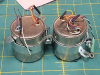
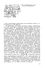
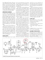
The architecture of X-Altra and LP797 MM preamp lightly resembles my PBamp-86 ["Radio Yearbook-86", p. 51 - I am attaching it below], only instead of a bipolar at the input, and the rest an input with a common source, then inverting the op-amp and a common frequency-setting NFB loop from the output of the op-amp to the source of the input transistor, almost like mine. Except for the needlessly stuffed thick capacitor C90 between the input stage and the op-amp.

What's in the negative? Andrew set the LSK389 mode with a drain current of 1.5 mA, and this is 3-4 times less than the current of the optimal mode, in which such fet has the minimal noise [see p. 68 of my book "Technique of high-quality sound reproduction", 1985 , I officially distribute it here https://www.patreon.com/posts/67628599 , and See also Fig.6-16 of JFE2140 datasheet]. We lose a few dB stupidly from scratch, and in addition, by the non-solder R80, to which R79 and R81 are also paralleled, we judge that Andrew does not suspect that the optimal input impedance can be much higher than the "standard" 47 kOhm [ https://patreon.com/posts/70415214 ].

The negative of the circuit design of the input stage is also its high sensitivity to supply voltage ripples. As the author himself notes on page 57 in the third paragraph from the bottom of the left column, PSRR is 0 dB, i.e. the power supply ripples are transmitted to the output of the input stage without attenuation! In order to prevent catastrophic deterioration of the SNR by the power supply, Andrew was forced to build a special active smoothing filter for powering the input stage on the second half of the U26 + R78 + C88 op-amp (at 1000 uF!), and for each channel its own.

I note that in Cy-XXI the two mentioned problems are practically absent due to the fact that in its architecture the first two stages are differential. That is, the noise of the current generator T1 also of course passes to the drains (outputs) of both input transistors FET1.1 FET1.2, but they are common-mode and therefore almost completely compensated as an input common-mode voltage by the second differential pair T2 and T3. For the same reason, interference from the supply voltage buses is also compensated. Those interested can familiarize themselves with the mathematics of processes in detail on pages 71-74 of my book www.patreon.com/posts/67628599 or by googling CMRR, PSRR.

Finishing with X-Altra MM corrector circuitry, let's calculate the number of separating capacitors: C90 + C82 (electrolyte) + C73 + C72 + C61 (electrolyte) = 5 in total, of which 2 are electrolytic. Too many, imho.

Let's move on to MC preamplifier. MC carts are fundamentally different from MM not only by an order of magnitude lower than the nominal EMF (at one kilohertz, typically 0.4 mV versus 5 mV), but also by two orders lower coil resistance (typically 12 Ohm versus 1 kOhm) and by 4 orders lower inductance (typically 75 uH versus 0.5 H). This is actually the lowest impedance and low level audio signal source. Russell for the MC preamplifier applied the recently fashionable complementary pair topology with a common base [ if the sclerosis correctly changes me, proposed at the end of the last century by Marshall Leach, https://leachlegacy.ece.gatech.edu/headamp/ ] on the mystery-covered "magic" bipolar transistors ZTX851/ZTX951.

The main design headache in this stage is preventing the ZTX851/951 from flowing significant input mismatch emitter current through the MC cartridge. In contrast to the huge 5000 uF input isolation electrolyte (see Moving coil headamps rev.2, Maxwell version, [ https://hifisonix.com/technical/mc-head-amp-circuit-compendium/ ] ), the floating supply from a 1.5-volt battery (Hawking and Planck) or the unthinkable selection of transistors with a base-emitter voltage difference of no more than 1 mV (Weinberg), Russell originally applied a DC servo on the OpAmp U1, approximately the same as in my Cy-XXI from version 4 and higher. Those, through the resistor R1 monitors the DC at the input and feeds it to the integrator comparator U1, from the output of which through R35R36 controls the base bias Q1Q2 so that the DC input is zero with an error of no more than zero bias voltage U1 OpAmp OPA2188, i.e. +-6 uV. For reference, I used OPA192 in DC servo, which has a +-5 uV offset, but it is better than OPA2188 in the sense that it is made using silent eTrim technology, unlike the 2188 chopper (interrupter), whose modulator / demodulator buzzes at several tens or hundreds of kilohertz, adding sticks to the input currents of the op-amp.

It’s clear with DCservo, but what else is done in Russell’s circuit for a pair of op-amps U3, U4 in each channel? And these are active smoothing filters for the collector circuits of these same ZTX851 / ZTX951. And with a bunch of thick electrolytes C17C18C9C10. And in addition, another 2x1000 microfarads in the separating conduits C11, C16. After all, this circuit is just as helpless against power ripples as the MM part of the Russell corrector, PSRR = 0 dB (second from the bottom paragraph of the left column on page 65 of AXpress February 2021). In terms of the number and capacity of electrolytes, this micropower MC preamplifier with a linear frequency response and a gain of 20 dB bypasses the 100-watt PowAmp on the TDA7294, such a construction is so big that makes it imposisble moutning neither inside tonearm nor even inside turntable.

But for the sake of fairness, we must admit that the scheme of his MC-preamplifier is interesting, because before him no one used DCservo @ input.

But in fairness, it should be noted that the circuitry of the Cy-XXI phonopreamp, with much less complexity and simply drastically smaller dimensions 20х45х3 мм [ 
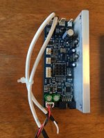
https://www.patreon.com/posts/insaidnyi-ot-vip-72574505 ], provides a level 553 nV/root Hz or 75 nV at 20 kHz or 74 dBA with respect to the standard 0.4 mV for a 12 Ohms head. Those almost the same noise as the trendy ZTX851/ZTX951 pair, but without the problems with thick electrolytes and power distillation and easily and trouble-free mounted in the optimal place - in the basement of the conclusions directly to the tonearm inside the turntable.

By the way, the author Dennis Colin, mentioned by Andrew Russell, from whom Andrew borrowed the architecture of the MM phonopreamp, formed his MC phono from the MM phono in the same way that I formed the Su-XXI_v.8_MС from v.7_MM: he simply added 20 dB amplification, and did not bathe with any additional preamps. As a prooflink, see the article by D. Colin from AudioXpress 2007, where on page 3 and Figure 2 you will find that trivial S1A, which is equivalent to replacing the 180 Ohm resistor in the Su-XXI_v.7_MM circuit with an 18 Ohm resistor in Su -XXI_v.8_MC. In conclusion, on page 2 of his article, note how much hassle was with the suppression of excitations of the op-amp. And add that Cy-XXI has 5 times less than "LP 797 Ultra-Low Distortion Phono Preamp". Can someone tell me how to call 5 times smaller than "ultra-small" ? 🙂
Conclusions. Vivat phonocore Cy-XXI 🙂) , no noise, no excitations, no distortion and no electrolytes, right? 🙂

Regards, Nick Sukhov

PS.
More detailed and illustrated info is here:
https://www.patreon.com/posts/pros-and-cons-mm-87586740
https://www.patreon.com/posts/skhema-gerbery-i-86997687

I remind you that in my phonopreamp it is exclusive in relation to the vast majority of others:

-minimum input capacitance 13...25 pF (depending on the version) with an input resistance of 150
kOhm; thanks to this, budget MM heads sound subjectively like top-end MCs.
-the original T-circuit of the frequency-setting negative feedback through R12C4 forms the time
constant tau4 ("7950 us" Amendment No. 4 to 'Processed Disk Records and Reproducing Equipment'
IEC 60098), and R10C3 provides aperiodic RF correction (a kind of "Neumann pole" compensator
"). Due to this, infrasonic interference is effectively suppressed, and the transparency of highfrequency
sounds is also ensured.
For reference: tau1 = 75 us is formed by the R9C3 chain, tau 2 = 318 us - by the R9R12C5 chain, tau3 =
3180 us - by the R11C5 chain.
-active current generator T1, coupled with the first FET1.1 FET1.2 and the second T2 T3 differential
stages provide good noise suppression from the power rails, preventing the need for overthorough
distillation.
-the second differential stage T2 T3 suppresses the fluctuation noise of the current generator T1 as a common mode
signal, minimizing the noise of the input stage.
-along the entire path of the sound signal, there are no electrolytic and generally separating capacitors at all.
-connection of the general feedback circuit to the output stage with a large output impedance ensures the constant
loop gain over the entire audio frequency range and thereby maximizes the overload capacity and minimizes the nonlinear
distortions as in the LF as well as on HF.

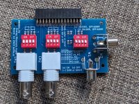
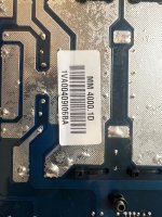
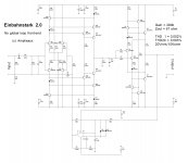
The numbering of the elements is according to the Cy-XXI_v.7 circuit and PCB gerbers for MM, from here: [ https://www.patreon.com/posts/skhema-gerbery-i-86997687 ]
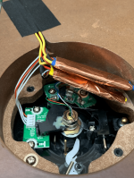
Attachments

  • SukhovPBAmp-Radioyearbook86_page51.png
    SukhovPBAmp-Radioyearbook86_page51.png
    331.5 KB · Views: 713
  • cyXXI@ttwithOPA192_jfe2140.jpg
    cyXXI@ttwithOPA192_jfe2140.jpg
    260.4 KB · Views: 709
  • cyXXIinsidemontage.png
    cyXXIinsidemontage.png
    715.4 KB · Views: 586
  • ztxElectrolytes.jpg
    ztxElectrolytes.jpg
    563.6 KB · Views: 673
  • Moving-coil-head-amps-rev-2_Maxwell.jpg
    Moving-coil-head-amps-rev-2_Maxwell.jpg
    234.3 KB · Views: 721
  • AX-Feb2021-ARussellXAltra_page64.jpg
    AX-Feb2021-ARussellXAltra_page64.jpg
    430.3 KB · Views: 771
  • AX-Mar2021-ARussellXAltraP2_page58.jpg
    AX-Mar2021-ARussellXAltraP2_page58.jpg
    343.5 KB · Views: 792
  • Colin LP 797_page_3.jpg
    Colin LP 797_page_3.jpg
    579.1 KB · Views: 790

Another DIY turntable bearing thread

I have read most of the threads on this subject so although no new ground will probably be broken here, here is my start at a DIY bearing methods.

3 pieces I have or I have ordered.
1720814279453.png

0.375 Ream

The drill rod is precision ground, -0.0002 to 0 tolerance.
I will attempt to bore and ream the bronze rod on my 80 year old Southbend lathe.
Will attempt to polish with my hillbilly wet fine grit sandpaper on a foam mandrel. I will try that first before investing in a hone.

This will just determine if I can machine a tight tolerance smooth running bearing in the radial direction.

Do I have any hope of success?

Dbx 290 Reverb problem- noise

Hi everyone.

These days since i have the time, I started repairing again (if possible) this simple DBX 290 (prohect series) reverb unit. I have to admit that i don’t use it anymore so i can risk a bit more.

The problem is that there is a lot of hiss, the more effect is mixed with the signal (when it’s full wet it’s at its loudest).

I replaced the filter caps, but nothing changed.
The direct signal is very good and clean.
The op amps look good (voltage etc).

Could it be something with the converters? Crystal clock?
Which Ic should i focus around? Can i find direct substitutes of such ICs ?
I have to admit that i haven’t got much experience on servicing the digital side of equipment. I usually deal with analog side or power supply problems.

I attach a link to the schematics in order to make things more obvious.

https://jumpshare.com/s/hLJpABpqGydbKFEPb19K

Thanks in advance

Do I need a recone?

I bought these Hemp Acoustics 8” coaxials at a very low price. Is the damage to this cone mostly a cosmetic consideration? These are essentially radian coaxials with a hemp cone. I want to start dialing in the dsp, but I read somewhere that a horn needs to have a smooth surface to work properly.

IMG_1609.jpeg


Would really rather avoid a recone since the cone in this material is not available.

For Sale Parasound Upgrade Kits

I just finished up a Parasound HCA-3500 mod/recap following @bigskyaudio's upgrade list he shared and have some parts left over that I had to purchase in bulk and need to sell.

I am 95% sure these parts also work in the HCA-2200 and possibly other Parasound models.

Here is what I have left over:
- Diotec Electronics Soft Recovery Bridge Rectifiers (these are VERY hard to get & I had to purchase a bulk amount at $21 each straight from Diotec Electronics)

- Holco 47k Resistors (purchased on eBay from West Florida Components for $1.15 each)

- PR9372 2.2k Resistors (purchased from Parts Connexion for $1.33 each)

I can make 2 kits with the above items and asking price will be $55 per kit. That will include shipping and please CONUS only.

Attachments

  • IMG_2180.jpeg
    IMG_2180.jpeg
    424.3 KB · Views: 65
  • IMG_2182.jpeg
    IMG_2182.jpeg
    449.5 KB · Views: 73
  • IMG_2186.jpeg
    IMG_2186.jpeg
    175.8 KB · Views: 66
  • IMG_2190.jpeg
    IMG_2190.jpeg
    143.8 KB · Views: 64
  • IMG_2185.jpeg
    IMG_2185.jpeg
    233 KB · Views: 66
  • IMG_2189.jpeg
    IMG_2189.jpeg
    241.8 KB · Views: 63
  • IMG_2187.jpeg
    IMG_2187.jpeg
    400.5 KB · Views: 67

Autoranger for soundcards

:cop:

Thread edited to keep chronological order of moved posts.

Introductory note from Jan carried forward from old thread.

Since I started my design for an autoranging attenuator/amplifier I have been posting in other threads sometimes hijacking them. So I asked the mods to collect those posts in a new thread here.

Comments invited.

Jan

---------------------------------------------------------------------------------------------------------------------------------------------------


Hi hochopeper,
If it's a 100 KHz source you need, an LC circuit could make an effective filter to hang after a crude sine wave source. Any of the HP oscillators like the 3336B or 3325A or B would serve quite well. Digital frequency accuracy, digital level stability. The L-C filter network would really do a number on distortion products.

Any of the XR2206 type circuits could also be used with a drop in stability, but still probably better than you need.

-Chris


Hi anatech,


XR2206 looks like the go, thanks! It's times like this that I regret not buying the -S model when I bought my Rigol scope.

Another milestone in the development of the autoranger!
Finalised and tested the cal procedure.
Especially calibrating the freq response for 0.1dB flatness out to 100kHz is a challenge if you don't have a fully equipped lab 😱

I now have a procedure that needs only an AC DMM with reasonable performance and a signal generator that can output 10kHz and 100kHz, preferably up to 10V or more but that's not critical.

The procedure directs you to do some measurements and enter values in a small spreadsheet and the spreadsheet then tells you what to adjust (cap trimmer) for which DMM indication.
For -20dB and -40dB settting, in both SE and BAL mode.

It's done faster than described!

Jan

Jan,

In your note above you mention a source that can provide 10kHz, 100kHz at ~ 10V ideally for calibration. The cheapo XR2206 kits seem to be set for 2V sine wave output. The datasheet has mention of changing a resistor and increase supply voltage to 25V to get more voltage out so no worries there. I don't want this thing to cost any more ($$ or time) than it needs to, should I care about the 2.5% distortion for this purpose? Or should I look for something a bit more sophisticated?


Regards,
Chris
Projects by fanatics, for fanatics
Get answers and advice for everyone wanting to learn the art of audio.
Join the Community
507,757
Members
7,887,080
Messages

Filter

Forum Statistics

Threads
406,168
Messages
7,887,080
Members
507,757
Latest member
jossdorn