That 1646 balanced line driver PCB

I made a pcb design for the That 1646 balanced line driver. I posted it on the dutch Zelfbouwaudio forum and Kostas alias TheShaman found it and contacted me if I had some spare pcb's.

I will post here some pictures, the schematic and gerber files so everybody can order the pcb's at for example Itead.

Attachments

  • Schematic.PNG
    Schematic.PNG
    44.2 KB · Views: 2,589

WTB Nutube / Triode Line-Level Preamp

I’m looking for a finished Nutube or conventional triode line-level preamp (no phono) to integrate with the following chain: Apple TV 4K → Rotel RSP-1576 Mk II (acting as DAC) > Odyssey Kismet Monos (≈200 W/8 Ω). Looking to build a 2nd harmonic rich chain with SS resolution 🙂.

Considerations
  • I’m open to a well-executed DIY build, factory kit (Korg Nutube, Nelson Pass B1-K, etc.), or commercial unit.
  • Must be fully functional and cosmetically reasonable; schematic or build notes appreciated.
  • Budget is flexible for the right piece. Will pay for shipping & provide label.
If you have something that fits, please PM with details, photos, and price. Thanks for looking!

Qspice is working in Linux

I hope that my success using CachyOS, a gaming-compatilble distro, translates to other Linux distros and hardware platforms. But I did get it working in at least one OS with a gaming software stack, on at least one hardware platform.

In the Qorvo forum some people made significant progress. They reported problems with a black background and pixelated graphics, and output that showed discontinuities in graphs due to improperly translated GDI calls from DiriectX 12 calls. But as far as I can tell, no one has reported it as fully working on that forum. One solution to the black background emerged but it wasn't for everone as it required patching source code and recompiling an old version of Wine. And even then frustrations remained.

I'm not seeing any of these problems. It runs smoothly and quickly on what I believe is integrated graphics with DirectX 12 calls being properly translated to Vulkan calls via vkd3d or vkd3d-proton. vk3d3 is how the gaming community in Linux has been slowly realizing DirectX 12 support in Linux to support Windows games.

Tracing my steps / How I got Qspice to work under Linux

Since Mike Engelhardt was using DirectX 12, and since DirectX 12 was a major challenge to getting Qspice to work in Linux, I decided why not install a gaming distribution and try it there.

1. Install a gaming OS. I installed CachyOS using the default kernel. This is on a notebook computer that has integrated Intel graphics and also a discrete nvidia graphics card. I tried to install the NVIDIA driver and it failed so I was forced to use the Intel integrated graphics which was fine because I knew that Vulcan support was/is excellent in Linux with Intel graphics. AMD graphics is also well supported.
Of note, the kernel that was compiled during the installation did not have NVIDIA graphics support. (This is not to say that it can't work with NVidia. I will try that next.)

2. Install the gaming software stack. The CachyOS has a Hello program that pops up after installation. From there, I entered the Tweak section and clicked the button for installing the gaming stack. This gaming stack is huge. It's about 6 GB and includes Lutris and Steam.
With all the software stack available, I decided to install QSpice using Lutris. Because Lutris is designed for getting things to run, for getting anything to run in Linux. This includes finding and remembering different components of Wine and other aspects of this challenge. (Direct installation failed, but I believe that it can succeed.)

3. Install QSpice. Since directly installing Qspice failed on Lutris, what I did was I installed Qspice freshly on my Windows computer and then copied the entire tree over to Linux. I then pointed Lutris to QUX.exe in that tree of files in order for it to run and then that worked.
I have attachments below that clarify the important points of how to configure Lutris for QSpice. The big picture is to select Wine as the runner, and to deselect DXVK and make sure you enable VKD3D. I deselected DXVK because I know that Mike is using DirectX 12 calls and not DirectX 11, 10 or 9.
Next, under runner options, the default runner for Wine, which is the latest, did not work. Close but no cigar. The one I had to choose was the System(10.6). No other option worked at this time.

That's it!

Needless commentary

My goal of moving away from windows is one step closer. CachyOS will probably be my OS of choice, unless I can get this working on another that I favor. It is fairly well understood that LTSPICE already runs well under Wine in Linux. So, one or the other will probably work. Then there is Micro-Cap, which I've read mixed reports regarding Wine, but probably it works well enough.

For Photography I'm going with darktable, probably the AppImage or Flatpak (not Snap). (As an aside, Photoshop users have reported success in at least CachyOS, and Photoshop has had a reputation for not running in Linux.)

Bye bye Micros*ft.

Of course, there's no guarantee that eventually Qspice will break in Linux, but at least we will have older versions that will run, and the older versions of Qspice are very good already I can tell you.

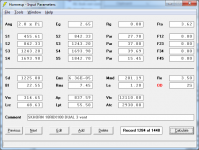
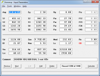
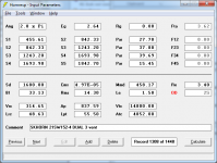
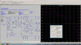
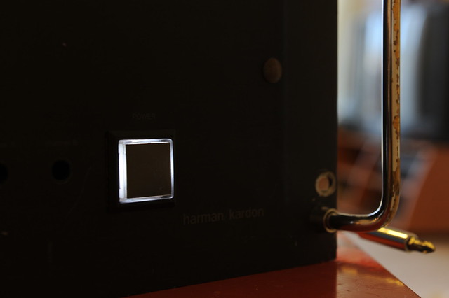
Seeing is believing:

Qspice_working_20250505_214901.jpg

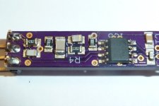
Harware and software details of this CachyOS installion on this notebook:
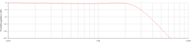
fastfetch_20250506_091523.jpg

Smooth graphics:
Screenshot_20250505_202052.jpg

Runner options panel, details within Lutris setup:
Lutris_working_settings_for_wine_runner_20250505_215235.jpg


That's a lot of pics. The other one I could show is the Wine version, but essentially it is version 10.6-2.

N.B. - CachyOS is an Arch Linux distribution. Therefore, this should also work in Arch Linux and also EndeavourOS. But please take note that it may not work and that it may only work on CachyOS because it has special kernels and drivers and it has its own compilation and optimizations for gaming.
N.B.2 - I also plan to try this with the kernel that is compiled with the NVIDIA-proprietary driver and also on a different machine that has only NVIDIA graphics cards and concomitant kernels and drivers.
N.B.3 - Arch-based distros are leading edge, rolling release distributions. They can be fragile, but I plan to approach this very conservatively. For those that don't know, rolling releases avoid major updates where, typically, things can break. Whereas a rolling release done conservatively will have continual small updates and no major discontinuities. The hope is for having smaller, fixable breakages here and there. My plan is to have a live USB nearby or have a second partition with a second installation with a more conservative base.

I pimped my Citation Sixteen! (or, resurrected?)

Bought a beaten-up Harman Kardon Citation 16 as a fixer-up unit and thought I’d fix whatever went wrong and it’d be my sleeper amp, only to end up with gutting this legend out completely. Now this amp has nothing but chassis and heat-sinks that are left over from the Citation Sixteen. It has two-channel Leach amp in it, with an output stage consists of 5-pair/channel ThermalTrak devices, NJL3281/1032 of On-Semi. By the way, could this be the first Leach Amp on TermalTrak output devices in this forum? Any ways here go the pics:

4830062951_c9bb33a188_z.jpg

ALL-BUCKLED-UP...will it be a rough ride?

4830063125_b3fce7586a_z.jpg

LITTLE DRIVERS…Can they handle the ark?

4830677548_5236b39f78_z.jpg

HEAT-AND-ITS-SINK
I piggy-back bolted some extra aluminum--scrap extrusion yet not particularly cheap🙁 from ebay-- to the center channel of the original Citation 16 heat-sink where the TO3s used to be to hopefully beef-up the heat-sinking capacity.

4830064835_88d11f5179_z.jpg

PCBS
Got these fabricated in China , cheap and in better-than-okay quality

4830676394_d5f5b66ab2_b.jpg

VAS
Voltage Amplification Stage assembled. I cut the GND copper foil to give the driver supply filter and the amplification stage supply filter separate ripple return paths after the PCB were made. The cuts show up on the component side as light marks mid way along the sides to the board edges

4830682060_0a074e9b6f_z.jpg

POWER-SUPPLY-BOARDS
These are hand-cut with a knife. The copper foils were later re-enforced with bus bars


4830678952_de79defbb5_z.jpg

PWR-CONNECTORS

Ring lugs over Erni Power-Tap was my choice of power connection

4830066195_a7893ccea1_z.jpg

POWER CONNECTIONS
Each Power-Tap connector receives 2 ring lugs. For the center GND there are 7 wires, 3 of them form a triple #14 gauge going to the speaker binding post, the other4 are driver supply filter return, amplification stage supply filter return, output zobel GND lead, and the signal GND reference. For the power connections there are 3 wires per each rail, one goes to the amplification and driver stage, and #14 doubled go to the output transistor common rail. Why double/triple the wires you ask? The butt end of my ring lugs is too large for a #14 stranded, plus they all say size matters😉


4830070965_b535fce619_z.jpg

BUS-BAR-BOT-COS
Current output board gets bus bars on the supply rails. I also put in pem nuts for easy attachment of the ring lugs. They were first pressed on the PCB into the plated holes, then got soldered to the copper foil.

4830684340_ece0f01e16_z.jpg

BUS-BAR-TOP-COS
The output node gets a bus bar too

4830675486_9fb65ba1b5_z.jpg

COS-BOT-WIRING
Ring lugs made doubled-up wiring easy

4830675712_c87aa8e58c_z.jpg

COS-DETAIL
Emitter resisters hooked up to the bus bar

4830062301_6e07da7ab4_z.jpg

COS-WIRING
Current output stage ready to go onto the transistor/heat-sink assembly. Oh, noticed the 2-conductor terminal block at about the lower left corner in the picture? They are temperature sensor terminals reserved for on-die temperature measurement or warning/protection. Four out of the 10 ThermalTrak diodes are hooked up in series and wired up to this terminal block.


4830064297_2f36028868_z.jpg

MODULAR-AMP

This is how the thing looks

4830676834_425f66e6cb_z.jpg

THE SHIELD
I sandwiched a third PCB of solid copper foil on GND in between the VAS and COS to cut down any possible capacitive couplings between the output stage and the input stage.

4830064105_ca403573b1_z.jpg

AMP-MODULE
Ready to go on the chassis and rock

4830068533_61006db836_z.jpg

AMP-OFF-CHASSIS
Powered up for the first time......with fingers crossed......

4830070215_27e2ce0930_z.jpg

BIAS-ADJ
Started bias adjustment. I finally set the idle at 400mA to give the heat-sinks a nice warm touch. Stability has been good so far since the amp went into service a few months ago.

4830061609_bffb3b02ed_z.jpg


LEFT-CHNL-TOP

Left channel is on the chassis. The Neutrik RCA jacks look good, don’t they?

4830063591_18cc832819_z.jpg

BINDING-POSTS
Are they too good?

4830674764_4bff979135_z.jpg

R-CHNL-OFF-BINDPOSTS
Another view with right channel off chassis


4830066585_d91dbdb710_z.jpg

TOP-VIEW
All put together! This is the "living room" of the chassis. The two black blocks sitting next to the RCA jacks are the speaker relays. These are automotive relays with 80A contact capacity. The transformer looks nice in the chassis to me, despite the fact it was scavenged from a broken Behringer EP2500 power amp.

4830065873_5cacde302a_z.jpg

spk-rly-RCA-jack
A close up view

4830679692_e1084cb3e3_z.jpg

BOT-VIEW
Let's go to the basement and take a look at all the supporting components. There are a few assemblies there, working on a secondary power supply. The secondary power supply transformer was scavenged from a broken CD player


4830680338_4b418420d8_z.jpg

INRUSH-LIMITING

This PCB has three relays of 12A AC contact capacity on board for the mains. One to connect through thermisters, the other two in parallel bypass the in-rush control when the rails have become stabilized. It also controls two out-board relays to cut in and out speakers. (more on this later). The coiled up twisted black/red wires in the middle (a bit unsightly) are not connected at this time. They are reserved for working with protection mechanisms to shutting down the power. The PCB in green behind the inrush board is a piece of scrap and work as a supporting base for other PCB assemblies to attach to.

4830067035_7022bb5816_z.jpg


DISCHARGR

It discharges all 4 power rails quickly when power is turned off. (more on this later) The black chunk in the lower right is the power switch with lighting. It came with 12V incandescent bulb in it, but I don’t like the yellowish color so I replaced the bulb with 4 white LEDs in series.


4830065655_9957532592_z.jpg

DC-DETECTION
It sends fault signals to the inrush PCB to have the speaker relay(s) cut out when DC is detected. It also lights up a warning LED indicating the channel in trouble.

4830685224_4c654b0720_b.jpg

IN-SVCE-TOP
Case closed.

4830073631_22148c112c_b.jpg

IN-SVCE-REAR
Ain’t her rear end smokin’ hot? 😉

4830072219_6ef1e3ec5f_b.jpg

IN-SERVICE-Front
Hey, how do you like her in new shiny shoes? The original neon bulbs in the fixture have been replaced with LEDs that serve as DC warning. They seem to be glowing in the picture but they are in fact not. When they do they’d be much brighter than that.
My Paul-Sue-Barton’s are happy. So is the wifie. Beethoven has never sounded more Beethovenian.

4830676666_ebf32d1bd1_z.jpg

TOE-OPERATED
The power switch is a push-button momentary switch so that one could easily operate with a toe and save his/her back. Here is how to:


http://www.flickr.com/photos/21102007@N04/4833640424/in/set-72157624460926929/
I’d get my dog to learn to do that for me if I had one.

About the Inrush PCB: (schematic will follow)
The big toroidal power transformer of over 1KVA and 80,000uF smoothing capacitance have made inrush current limiting a must. This circuit is based on hard-wired logic/timer devices, it controls the mains power relays and speaker relays. It works on a 12VDC secondary supply. This was laid out on a two-sided PCB that requires some basic SMT soldering skills to assemble. The circuit works with a lighted push-button switch with momentary contacts as the power switch, each push starts a 5-second time window during which the switch itself is disabled and the switch lamp flashes. When start from standby the soft-start relay will engage for as long as the time window lasts (5s), the mains power is applied through three GE CL-40 NTC thermister in series (15 ohms in total at room temperature). This will limit the inrush current and charge up the main caps in a controlled manner. The main caps should be charged up well within the 5-s time window and the rail voltage flats out. A flat-out detection circuit will engage a power-good monitor and if a power-good is positive the circuit enters power-on mode, the main relays (two in parallel) will bypass the inrush limiter and connect the primary winding of the power transform directly to the mains supply, the lamp in the power switch stops flashing to glow at a normal brightness, the speaker relays will also engage at the same moment given that there is no DC detected at the amplifiers’ output. The soft-start relay then cuts out at the end of the 5-s time window. If no power rail flat-out is detected or no power-good is detected during the 5-s time window, the main relays and the speaker relays will not engage, and the circuit returns to standby mode at the end of the time window, the lamp in the power switch then stops flashing to glow a dim light. Pushing the power switch during power-on mode will simply disengage power relays and speaker relays, and a 5-s time window follows to allow the main caps to be discharged deeply enough prior to responding next button push.

About the Discharger: (schematic will follow)
It brings main caps down to under 5V a few seconds of power off. It was built on prototyping board. The discharger is engaged whenever all the mains power relays cut out, and disengaged when any of the mains relays actuates. There are 4 jumpers on the board that allow for disabling the discharging operation. I used 4 photo couplers to isolate the control side from the audio GND, as well as audio GNDs of left and right channels. Such isolation also allows a very simple and uniform circuit implementation on all power rails using power MOFETs of one single model.

DC detecting circuit: (schematic will follow)
It works in tandem with the soft-start PCB to cut out speakers when DC presents at the amplifier output, it lights up a warning LED of the channel in trouble too. Built on prototyping board.

To be implemented: (schematic suggestion welcome)
An on-die temperature measurement/warning/protection using the roughed-in temperature sensor.

Dorati NOS DAC kits

Orders now are open on Dorati NOS DAC kits - PM me and be sure to include your payment method and location so I can quote you inclusive of fees and shipping. Dorati offers a sound quality upgrade over its predecessor 'Kubelik' but retains the same physical footprint of 81mm * 50mm, slightly smaller than a credit card; the maximum height is 24mm. The design is non-oversampling (i.e. there's no digital filter on-board) uses passive I/V and has a discrete output stage. What sets it apart from typical NOS DACs is the use of an LC filter prior to the active stages. The input format is I2S (three signal wire) at 44k1/16bits. BCK can be 1.4 or 2.8MHz, no MCK is required. Output is CD standard 2VRMS and headphones at 300ohm impedance and above can be directly driven. Power supply requirement is a single 12-15V rail at 150mA max. There's a digital invert function, selectable by a 0R resistor. Schematic may be found here : Dorati schematic updated 6.23
Dorati can be used in a pair of boards to create a balanced output DAC. To achieve this you'll also need an I2S splitter board which is sold separately. The splitter changes the normal L,R stereo configuration of I2S into two outputs: L+,L- and R+,R-.

Preferred payment method is via Wise which typically adds a 2% fee. Our receiving currency is CNY, alternatively USD or Euro. PayPal may also be used, in USD but will attract higher fees, about 6%.

Price for a Dorati kit : 168RMB (~$25)
I2S splitter board to create balanced output DAC : 90RMB

Shipping is in addition and depends on your location and speed of service. Courier (FedEx, TNT, DHL) typically takes 8 - 10 days and e-packet four to eight weeks. Not all locations can be serviced by e-packet though.

FAQs

What else is needed to turn the built up Dorati kit into a fully operational DAC?

First you'll need a well regulated low noise power supply of 12 - 15V rated at 150mA or higher. An LM317-based board set to the correct voltage will suffice if you already have an unregulated supply (like a typical wall-wart). I don't recommend switching supplies due to issues with common-mode noise, its very hard to filter out. This dis-recommendation though only applies if you're building a stand-alone DAC. If you are building the Dorati into a system with the amps in the same box then switching supplies are perfectly fine but I would then recommend an LC filter to reduce the switcher's output ripple, a direct connection is likely to reduce SQ. We can supply an LM317-based board with either DC (for unregulated DC) or AC (for a transformer) input option. LC filters for SMPSUs are on the drawing board as I write this, best enquire if they've become available.

Second you may need a digital interface card. I say 'may' because some digital sources produce I2S directly (like Raspberry Pi, many dedicated SDcard players) but most sources will either output USB (like a PC or laptop) or S/PDIF coax (a CD or DVD player) or Toslink. We can supply a card for interfacing one (or more) of those sources to Dorati's I2S input. A CM6631A-based card for USB input is the premium choice as it operates under 'async USB' which is the lowest jitter. A mid-range alternative is an interface based on an STM32F4 microcontroller - while still low jitter, its output is not as clean on start/stopping as with CM6631A. TE7022 is another suitable USB controller chip in the mid-range bracket. In the bargain basement dept are the interfaces based on 'adaptive USB' such as CM108 and PCM270X.

There's an advantage in going for a USB interface that operates on full-speed USB (12Mbits) rather than high-speed (480Mbits). That is - you can buy a cheap isolator device to use with it and isolation from your PC's common-mode noise is most definitely worth having from a SQ point of view. 480Mbit isolators have recently become available but are much more expensive (price ratio in the region of 10:1 compared to 12Mbits). For my DACs I have come to the conclusion that isolation is more valuable than ultimate lowest jitter. Full-speed USB interfaces only go up to 96k sample rate so if you're someone who needs 192k then look out for a high-speed isolator.

The S/PDIF board we recommend handles both coax (two inputs) and Toslink. Further, it has a switched I2S input - this is useful to accept an I2S stream from a separate USB interface card to facilitate a USB input. A single pole switch acts as source selector, cycling through the four sources. An OLED screen is an option to indicate the selected input. If your DAC supply is 12V, you can directly power this card from the same supply as you use to feed the DAC. The simple coax/Toslink board needs a regulated 5V PSU which can be implemented via a regulator from the DAC supply.

Third you'll be wanting some output sockets, typically RCAs so you can connect your finished DAC to your amp or preamp. Or if you're feeding high impedance HPs, a 6.3mm (or 3.5mm) TRS socket. We can supply these. We also have a PCB for mounting a pair of RCAs which makes connection a little easier.

Lastly, and this is obviously optional for a DIYer, is a case. We haven't supplied cases in the past because they're so heavy (i.e. expensive to ship).

Whilst these links all worked when I posted, Ali links go stale very quickly so beware. CM6631A is rapidly becoming unobtainium, we couldn't find a single Taobao seller with stock :

USB CM6631A card examples : Aliexpress CM6631A USB-I2S
USB STM32 card example : Aliexpress STM32USB card
USB TE7022 card example : Aliexpress TE7022 USB interface
USB PCM270X card example : Aliexpress PCM2706 USB interface
USB full-speed isolator example : Aliexpress USB full-speed isolator
USB high-speed isolator example : Aliexpress USB high-speed isolator
Multi-input S/PDIF card : Aliexpress S/PDIF Toslink I2S switcher
Coax/Toslink S/PDIF card : Aliexpress DIR9001 S/PDIF receiver

Do I need special tools to build and test my Dorati kit?

You'll need some fine diameter solder (0.3mm is recommended), a temperature controlled soldering iron with a fine bit and a pair of tweezers. A magnifier comes in very handy but that depends on your eyesight. Desoldering braid is helpful for correcting mistakes. If you've never soldered SMD before then maybe Dorati will be too challenging for a first project as there are around a hundred parts. However none of them are microscopic (the smallest is 0805) and none of the ICs has pins closer together than 1.27mm. For testing you'll need a DMM (digital multimeter).


What's supplied in the kit?

There's a picture directly below of the contents (to be added) : the bare PCB plus all the components that mount on it (resistors, caps, inductors, LED, ICs etc.). Given that 0805 sized components are incredibly easy to lose, we include a spare or two for each value. Input, output and power are supplied via 4pin Molex-style headers, we supply the mating half with crimped wires to these too.


What, if anything, is unique about Dorati's design?

Commercial NOS DACs typically have minimal filtering after the DAC chip itself. Dorati has two kinds of filters resulting in a 5th order overall lowpass response - a 3rd order passive filter prior to I/V and a 2nd order active filter afterwards. The passive filter prior to any active stage improves subjective dynamics - it means the I/V buffer no longer 'sees' a step waveform out of the DAC chip, rather a continuous signal. The active filter provides 'NOS droop' compensation - meaning you get a flat frequency response to around 17kHz whereas a typical (not every) NOS DAC has roll-off approaching 3dB by 20kHz. No opamps are used, the analog signal processing stages are all discrete transistors. Dorati's DAC chips are 'multibit' but they're not strictly speaking 'R2R' as internally they use no resistors. Instead capacitors are used as elements in the DAC which have their charge constantly refreshed (similar to the DRAM in your computer) to compensate for any drift.


Kit_contents_20220609100425.jpg


Dorati Soldering Guide rev.jpg

Small Driver for MEH

I have been designing another small MEH.

So far I have been designing it around the Faital Pro 2fe24 however from doing measurements the distortion is mega high at 10% THD at 10W around 600hz. It's still mega high on less power minimum 2% or 3% THD

Edit: thought I would add that this distortion is even just with a small rear chamber and no front chamber/ports/horn

1745482469615.png


This is the rear chamber I made for it: (I got the 3d file from Faital Pro and seal it with a small o ring at the top)
It is fully sealed, you can tell because the cone is harder to move than when it's free.

20250424_091136.jpg


I'm going to borrow some peerless 830970 to try which look a bit more suitable

Does anyone know of any other good drivers that could be used in a MEH that are 2" or 2.5"?

I'm trying to push the mid up to 2.5khz at least so I need a 2" really
  • Like
Reactions: Naturlyd

Next level Active DSP Crossover

I'm currently multi-amping my LaScala clones, using a Dayton Audio DSP-408 active crossover. There is a lot to like about it in terms off functionality: 4 channel in, 8 out; 10 bands of parametric eq per out, up to 24db Linkwitz-Riley/Butterworth/Bessel filters and a 20hz-20kHz response. It had a decent UI, with bluetooth/iOS connectivity and a windoze interface, as well. However, I would like to improve the noise floor, is has a slightly perceptible hum that is present when music isn't playing. It's entirely single-ended, but I would prefer balanced, at least as an option. Finally and this is the biggest issue for me: the DAC is limited to 48Hz, 28-/56 Bit processing, which regardless of whether it's audible or not, effectively nullifies my Schiit Audio Bifrost 2's 192Hz, 24 bit capabilities for hi-res audio file playback.

What options are available to maintain the functionality aspects that I like about the Dayton Audio DSP 408 (ins, outs, 10 band PEQ, filters & frequency response, ui and relative affordability) with better processing, at least 96Hz/24 bit, but preferably 192Hz, 24 bit, balanced inputs and outputs? I know there are pro options from companies like Ashly that are more expensive than I'd prefer and more affordable pro options from dBX, Behringer and others skimp on PEQ, or ins/outs and/or have poor UI functionality... I'd prefer to keep in the $500 ballpark (I'm ok with used components) and this is a big ask, have either iOS or Mac OS UI.

can this be done?

IMG_6253.jpeg

For Sale Tungsol KT-120 Tubes - Matched Quads & Matched Pair

I have a number of matched quads of Tungsol KT-120 tubes never used except for testing and in original boxes. Price is $175 per quad plus shipping. There is one matched pair I will sell for $100 plus shipping. Will only ship to US lower 48. All sales "as is" with no warranty expressed or implied. I have not sold here before but have sold on USAudio Mart (tony4660) and Audiogon (clio09).

KT-120.jpgQuad #1.jpgQuad #2.jpgQuad #3.jpgQuad #4.jpgQuad #5.jpg

ZOUDIO AIO4CH: 4-channel amplifier with DSP and Bluetooth

I want to introduce a new product I have been working on for the past years.
It's now available for pre-ordering, which will be shipped in the end of februari, in order of payment.

ZOUDIO AIO4CH: 4-channel amplifier with DSP and Bluetooth


Features:
-4x45W class D amplifier (can also be configured as 2.1 or 2.0)
-Bluetooth V4.2 APT-X with True Wireless Stereo
-Configurable DSP
-Easy to use Windows configuration tool
-Small format with high efficiency

Screenshot configuration tool:
Inteface3.jpg


As can be seen, a lot of the settings can easily be changed, such as:
-Start and maximum volume
-Battery protection voltages
-Input (left/right/mono) and output (4.0/2.1/2.0) configuration
-13 general filters (equalizers) en 5 filters per channel (crossovers)
-2 equalizers which can be enabled with a button (e.g. indoor/outdoor, bass-boost)
-Volume dependant (dynamic) equalizer
-Delay per channel

This thread can be used for questions about specifications and how to use the products. Remarks and suggestions for improvement are also welcome for this and future products.

Productpage (datasheet, configuration tool download, ordering): click here

Attachments

  • IMG_20200104_134624.jpg
    IMG_20200104_134624.jpg
    811.3 KB · Views: 4,796
  • IMG_20200104_134718.jpg
    IMG_20200104_134718.jpg
    445.6 KB · Views: 4,651
  • Like
Reactions: aditya

MF A1, Kudos to Tim de Paravicini, Ode to my Youth, Babelfishing

Need to get this out of my system ........

When I was a Kido, just barely moving with my first attempts of building amps and preamps from scratch, desperatelly wandering through any available printed sources ( no www yet) in search of/for Holly Grail .... my good friend just acquired specimen of which is later to be one of my all ever favorite amps - Musical Fidelity A1

(what did I knew that I'll have damn long list of my fave amps, not necesarily good ones or special in any tecnical or performance way, but heck - guy can have feelings, liking things just for liking sake :rofl: )

Anyhow - not much time did pass, I had it in pieces, first to figure out schematic, and then maybe to think something clever (hell, yeah :clown: ) to make it better

Not much time after that, I had built my own, by wonder it worked right from the bat, by wonder I did guess right what output transistor are (ignore thing that I really knew just 2N3055 and needed to chase its "complementary" ..... so I had proper beginner's luck guessing right ones - 2N3055 and BDX18)

And - no wonder that I made exactly same mishaps as mishaps being implemented in original - I did use 100VA mains Iron for 80W of juiced juice, and mine also had beautiful thermal arrangement as original, resulting in oh boy!!!!!!!!!! temperature of heatsinks

Later, when we did some head to head comparison between friend's original one and my "Clone", awe was that "Clone" sounded better - simply beause I did made just power amp portion, really not being able to include preamp section in said moment, planning that to add in later time

Speak of beginner's luck, again :clown:

Conclusion - "Clone" did sound better with line level sources, preceded with just 10K pot, than original one having all bells and whistles

Then we did go wild, trying tube stage in front - finding some "modern" solution - ECC88/6DJ8 fed with humongous voltage of 30V ..... it did help some - fact that it was loaded with current source .....

What we did know that MF will follow same easy commercial pats some later, nicely feeding hordes of us ignorant imbeciles ....... in fact - nothing wrong with nice little pleasing boxes, but I later did found following Myths and Legends somewhat disgusting :devily:

Do I need to say that it sounded even better with "tube" stage, however flawed it was?


.......................................... fast rewind to www time, I started chasing Holly Grails in every possible direction, beside other things I did found some few itsybitsies about my (then) still fave amp

If you fancy some reading, see attached pic (schm , few posts down) and visit Mark Hennessy page https://www.markhennessy.co.uk/mf_a1/

M. Hennessy is getting most of facts right ....... and I have impression that he's extremely polite, whenever anything worth commenting he did comment :devilr:


I'm going to be extremmmmmmely polite, not commenting anything about original commercial MF A1, neither first Gen, nor 2nd (just a gimmick, really, having USBandwhatever) nor present - 3rd or, rather, proper 2nd Gen

In last few decades, I had at least a dozen on my workbench for service and improvement, had at least 4 called "mine" ....... where last one of these 4 is still around (serving one of my friends)........... while my described clone is still somewhere around, supposedly still mine but I really need to stretch my gray cells to decipher where it is exactly .............

huh, tired of typing

My AT420E(OCC) Cartridge - a confused look at the electrical side

In the last few days off, I have been somewhat confused and have tried to collect enough reasonable data for a possible replacement circuit using the usual home remedies. I don't know whether I succeeded or whether I was able to develop a common thread; the more diagrams one plot, the more confused the scenario becomes. I deliberately left out the interesting mechanical side, because how can one approach it reasonably well with home remedies? Of course one can think about the elastic side between the cantilever and tip and the plastic disk, but on average we always come to a conclusion, reso fo is always less than 35kHz and the cutoff fc moves from 61kHz to 32kHz ... outside to inside.

Perhaps we can develop a test procedure, a common thread, together at this point.

Attachments

  • AT420E - a coil.pdf
    AT420E - a coil.pdf
    843.9 KB · Views: 99
  • 47k_parallel_180pF.png
    47k_parallel_180pF.png
    15.2 KB · Views: 131
  • 150k_parallel_12pF.png
    150k_parallel_12pF.png
    14.8 KB · Views: 132
  • AT420E_Modell_1.png
    AT420E_Modell_1.png
    3.7 KB · Views: 126

Buying tubes on eBay, who to trust?

Guitar amp enthusiasts are blessed.
They can buy tubes from tube stores everywhere.
Those of us who favour the audio tubes of old, like the 26, 45 and other obsolete goodies are cursed.
Trying to find these types in the regular tube stores has proven difficult, and eBay seems to be the only option.
But who to trust, since anyone can state that what they sell is NOS, unused, tested and found in excellent working condition.
Despite all promises, what you get in the mailbox may be tubes at the very end of life, gassy and generally unusable.
I hope that someone here have some experience with thrustworthy eBay sellers and would be willing to share info on this.
-Thank you in advance . . .

New version of my tonearm phono preamp

This is sort of a continuation of previous thread https://www.diyaudio.com/community/...er-light-phono-amp-inside-the-tonearm.268400/
that one diverged rather hence new thread.

The new version features a lower noise front end, but is a bit more cramped as a result.

P1050755.JPG

P1050754.JPG


There is a NE5534A RIAA stage at the left, one on each side for L+R.

The board is 8mm wide and 95mm long.


P1050756.JPG


Then two 2nd-order Sallen Key stages implementing a 4th-order Butterworth high-pass "rumble" filter, detail on one stage (two channels):
P1050757.JPG


The opamp here is NE5532A dual.

The response to 5mV rms 1kHz input, both channels:

new-ne5534a-tonearm-preamp2.png


No special precautions against mains hum, other than short leads to the QA403 analyzer, and the high freq hash is probably from laptop or LED lighting or both. Power was +/-9V from batteries, the QA403 is galvanically isolated which no doubt helps.

And the response, weighted with inverse RIAA:

new-ne5534a-tonearm-preamp-resp-riaa.png


The rumble filter slope is clear, about 14dB down at 10Hz and ~36dB down at 5Hz.

Schematic:
Screenshot 2024-04-20 at 09.30.29.png


Its a little hard to read, but the RIAA feedback network is 3.3nF || 22k and 12nF || 270k, with 330R to ground. Caps are PPS and resistors thin-film, 0805 and 1206 size

Attachments

  • P1050756.JPG
    P1050756.JPG
    31.7 KB · Views: 169
  • Screenshot 2024-04-20 at 09.28.23.png
    Screenshot 2024-04-20 at 09.28.23.png
    100.3 KB · Views: 153

Old Variac

Hi Folks,

I've had great success here finding answers to unordinary questions in the past, I figure I would try again.

Over the weekend, I picked up an old Variac at an estate sale. I did a quick test and it works, and is fairly accurate, so I would like to go ahead and make it a little safer by adding a new 3-prong power cord, fuse and new 3 prong female receptacle for the load side.

However, I am having a bit of difficulty trying to source a shallow 3-pronged receptacle. The one currently installed is very shallow. It's only about 1/4"-3/8" deep from the inside of the Variac cover to the end of the receptacle. Everything I am finding is over 1" deep, and I don't think I have the room inside the cover for that. The other issue is that the current plug is round, which are difficult to find. But that is a minor problem, I figure I am going to have to do some modifications anyway.

I've attached a couple of pictures for your review.

I checked Mouser, Digikey and Amazon without success. Does anyone have an idea where I can find a shallow 3 prong receptacle like this? Or should I just stick with the 2 prong and move on?

Attachments

  • 20250603_231109.jpg
    20250603_231109.jpg
    430.3 KB · Views: 71
  • 20250603_231120.jpg
    20250603_231120.jpg
    411.2 KB · Views: 63
  • 20250604_171231.jpg
    20250604_171231.jpg
    276.3 KB · Views: 64
  • 20250604_171248.jpg
    20250604_171248.jpg
    297 KB · Views: 66
  • 20250604_182954.jpg
    20250604_182954.jpg
    406.6 KB · Views: 70

More P3A

Been way too long and missing many wonderful things happen in the forum
to busy sorry to say .
Most of you know that i currently construct P3A and allready produced 5231 different PCB implementing mods and different styles .
2026 will be 20 years ( man time flyies ) that i am doing that .....

So since i am having a brake from too much work ( had a really rough last year concidering volume of work ) i am willing to construct once more but this time with regulated rails or capacitance multiplier ....

Quad did in the past , Naim did in the past and soon (since classAB is a dead end ) we will see one of the big names of hi end comming with one machine ( range 50K ) that will be a typical hi end class AB ( includes extreme enclosure style and loads of transistors ) but this time with IGBT regulated rails .

Question is that if anyone thinks that is going to be any audible benefit from that ?
Question is that if this benefit will apply from low listening level till clip ?
Question is regulated rails or capacitance multiplier and why ?

My only previous expirience was with QUAD wich the all thing was single rail, capacitor coupled, sorry excuse of amplifier circuit .
BUT !!, people that used them actually as pro amps in small bars said that they sound very good , amplifier is indestructable and impossible to destroy a speaker with it ... ( probably this has not much to do with regulated rails , but mostly because is capacitor coupled )

Place your comments please
i will be more than happy to listen

thank you

For Sale XA252 PoP R1

I have for sale a few more PoPs, R1 this time with better layout and performance.

These can be tuned to have more or less flavor so it can suit all tastes by changing a few key components in the front end. Depending on your taste you can mention what exactly you want, less flavor meaning less thd.
From the strongest flavored to the light flavored at some power levels the thd is half.
Please see the new thd graphs at the bottom of the post where I compare the same module setup in 2 different ways.

24-06-20 18-29-11 7334.jpg


Since some time I go ahead with the Xa252 PoP being the reference amp in my system.

It can work from +/-16v to +/-24.5v. Bias is preset at 1.4a.

The schematic looks like this
Screenshot_20.jpg


Stable as before when handling square waves
24-06-18 12-18-57 7279.jpg


The new pcb has same drill hole pattern as R0
pop fixing.jpg


And here some thd measurements
1w4r.jpg

1w8r.jpg
10w4r.jpg
10w8r.jpg
20w4r.jpg
20w8r.jpg
40w4r.jpg


All modules are tested and working. If no preference for the thd the modules will ship with the stronger flavor.

Later edit:
I am adding a crc psu pcb together with the modules for the same price.
IMG_9493.jpeg


Price for 2 channels and the crc psu pcb 160€


Later edit:

Someone said he uses a 5U400 enclosure for his builds (which is quite big) and is able to take 1.8A bias at +/-24V. So the user wanted to use the modules at a higher bias(1.8A) than the 1.4A as I set them.
With a higher bias for the output stage you will get more power output in class a(which you have plenty already with 1.4a bias) but also a bit more thd at high output power. So I think this time it`s better to keep it at 1.4A.
The maximum bias that can be set for the PoP modules is 1.6A so I took the measurements here, didn`t bother to modify the tested module to go to 1.8A. It isn`t really needed for the PoP.
bias 1w4r.jpg

bias 1w8r.jpg

bias 10w4r.jpg
bias 10w8r.jpg

Current drive leaked circuit diagram

Hello!

https://images.app.goo.gl/Z2ubMvpESb9A7Aiq8

A standard laptop charger can be used for power supply, where the output power is 5 watts and the distortion is < 1% (2nd and 3rd harmonics). In principle, the supply voltage can be increased up to 30V (Pout ~ 10 watts). The efficiency of this amplifier is about 20%.

The adjustment important if you really want full output power. With R15* you set the voltage at the collectors of T4, T5 and T6 to Vcc/2 (e.g., +19V/2 = +9.5V). Use R13* and R14* to adjust the currents through T6 and T5 (for Vcc = +19V it should be 0.6A each).

The circuit has an automatic soft start. If R15* is too large, it can take up to 0.5 minutes, until the amplifier becomes active.

Best regards

LED light bulbs

Has anyone calculated savings compared to Incandescent bulbs?

I recently bought a box of 12 100W 5000K 1500Lumen bulbs off Amazon to improve the lighting in my house. At near 70 years I have difficulty seeing without lots of light.

I measured the power consumption and did a rough comparison to 100W 1000Hr life bulbs.

It looks like over a 1000Hr life of the incandescent bulb, the LED saves about $17 at a presumed electrical rate of $0.19/KW-HR (11.5W LED consumption). Given that the 25000 hr life is inflated, and using 10,000hrs instead.

I also bought some 200W equivalent 3000Lumin 5K temp bulbs that actually measure 23W consumption.

Isn't technology great?

schickeRIAA

MC phono preamp / shunt feedback with inverting INA head

EDIT: actual schematics see post #28


i just finished the first prototype of my phono stage design 😎

the last years i primaly used MC pickups, so the idea was to build a phono pream dedicated to MC, not the usual MM with head amp. important for me:

  • DIY friendly, i.e. through hole parts, easy to source, low parts count
  • good compromise between noise and headroom
  • proper RIAA acuracy
the overall architecture consists of a THAT 1510 as input stage and a shunt feedback RIAA stage. the gain of the input stage is 40dB, this can happily handled by the CFA INA, noise is pretty low. also the INA corrects the phase reverse introducd by the shunt feedback stage. a 2u2 capaciter eliminates any offset voltage and builds a modest 6dB high pass with 15Hz corner to strip away infrasonic frequencies before applying the bass boost. the feedback network is class C to save capacitor cost. i started the network calculations with the capacitors, because E6 has limited values and i wanted to avoid armadas of parallel capacitors. the ratio between the to capacitors in the class C network ist appr. 2,9, so 2*2.2/1.5, 2*10/6.8 or 2*6.8/4.7 are pretty close.
the opamp is a JFET type. i tested also a LM4562, but it realy didn't sound as good in this position.
power supply is pretty standard, delon voltage doubler, LM317/337.

Thomas

Attachments

  • schickeRIAA.png
    schickeRIAA.png
    227.9 KB · Views: 392
  • image0.jpeg
    image0.jpeg
    21 KB · Views: 354
  • image1.jpeg
    image1.jpeg
    18.9 KB · Views: 220
  • image2.jpeg
    image2.jpeg
    14.3 KB · Views: 217
  • image3.jpeg
    image3.jpeg
    14.9 KB · Views: 352
  • Like
Reactions: hbtaudio

Some speaker driver measurements...

Dear friends,
there are many enthusiasts of loudspeakers building here so I thought this link would be very useful for someone.

http://hificompass.com/en/speakers/measurements

It is needed to register at the website to have an access to the speaker drivers compare feature.
With no registration one can click on driver model name in the table and get to the speaker driver measurements page.
There is the mesurements description above the table. Just click on it.

To moderator - sorry if I place this thread in a wrong place, you can transfer it in the correct place.

Best regards,
HiFiCompass

For Sale Set of capacitor board for single supply SMPS

I have for sale a set of two additional capacitor boards. They were designed to improve performance of single rail SMPS when powering D class amplifiers (3e, Sylph Audio...). Dimensions of the board are 95x50x40(height with spacers) mm. Each pcb board consist of:

1x Nichicon FW 1000uF 63V
2x Nichicon FW 470uF 100V
1x Nichicon KZ 100uF 100V
1x Mundorf 1uF 250V foil capacitor


Price is 25 EUR (for set of 2) + post costs + PP fee

Attachments

  • cap board II.jpg
    cap board II.jpg
    424.6 KB · Views: 96
  • cap board I.jpg
    cap board I.jpg
    358.9 KB · Views: 93

Irregular shaped MLTL / Hornresp question

I am working on a tall, skinny TMWW speaker.
I have seen the comments that a tall, skinny speaker is a MLTL due to its nature, whether I call it a basic bass-reflex or not, so I thought I would take that seriously and model it as a MLTL in Hornresp.

To make things work, I would seal off the top portion with the midwoofer and have a simple rectangular volume for the two woofers. I model the woofer placement as the center of the two actual woofers. In Hornresp, I can actually get a very good model for this. BUT, while the overall size is acceptable, the pink shaded area is wasted space (see image to the left).

Would it work, and is there a way to model it in Hornresp, to open up that area and have an irregularly shaped "line", as in the image to the right?

1749079394401.png
1749079498059.png

True Wireless Stereo (TWS) Bluetooth for Speakers

True Wireless Stereo (TWS) Bluetooth for Speakers

Hi Folks,
I am looking for a way to have two physically separated wirelss Bluetooth speakers play stereo. I do not want a wire connection between the left and the right and I want it to connect like a single BT device. I know that this is possible as I have several earbuds and headphones that do this. They ususally call this TWS (true wireless stereo) and I have searched and searched but have failed to find either a line level TWS receiver pair or a simple Class D amp pair with TWS. I know that if I hacked into the wireless earbuds, I could indeed take the headphone outputs and connect them each to a power amp and make my own TWS amplifier. But that seems silly. Surely, there must be a commercial off the shelf solution for this already?

The idea here is to have a stereo BT speaker set, physically placed in a room. I do not want clutter from a wire running from the left to the right one.

I do not need a lot of power. 5W or 15W woud be enough.
  • Like
Reactions: mondogenerator

A2CMx: AmyAlice DC filter and cap multiplier for SMPS

First of all I have to mention that this thread started following Mark’s idea found in this thread https://www.diyaudio.com/community/...apacitors-smd-assembly-max-3a-max-48v.405099/
I needed clean power for a vfet follower amplifier that was getting its juice from a 90w laptop brick followed by a sk80h buck boost converter. Because there was also low frequency noise beside the high frequency one I decided to add the cap multiplier inspired too by an earlier design from same Mark.
So practically the only thing I did was to play around a bit in my pcb design software to put together the pcbs.
It all started here https://www.diyaudio.com/community/...d-assembly-max-3a-max-48v.405099/post-7505998

And then after that this part followed..

A few users asked by private messaging about the single rail pcb but also about a dual rail or bipolar pcb. At the time I had only the single rail pcb so I drew the bipolar version. I call it bipolar because how it`s designed but it can be use as a dual too.

For the bipolar version I created 2 pcbs. One that has a single ground plane for both rails and another that has the two ground planes separated. Initially I done the single ground pcb and then asking Mark for a suggestion I got the dual ground pcb.
On the dual gnd pcb you have the possibility to connect the gnds at the input or at the output of the filter.
For each pcb I will attach the schematic, bom, a few photos of how it looks and the gerbers.

I was planning to release these gerbers in a week or two after testing my single rail unit(I don`t intend to build and test the dual/bipolar pcbs) but then realized that it will be a bit late for those who want to have something to solder in the holidays period.

The dual pcb can be used as both positive, positive and negative or both negative filters.
The lower half of the pcb is designed for a negative filter but if you reverse the electrolytic caps and instead of the pnp bjts you place the npn ones as on the positive rail you can make the bottom part a positive filter so you will have 2 positive filters on same pcb.
If you need two negative filters on same pcb you will need to reverse all electrolytic caps on the upper half and instead of the npn bjts place pnp ones. Simple as that.

Edit1: all the boms miss the heatsink that is needed on the bd139/bd140 devices. After I build the single version I will edit all the boms with the needed part.
Edit2: after testing the single rail pcb I found that there is no need for a heatsink for the bd139/140 devices so nothing to add to the boms. Same thing is valid for the bipolar version too.

Attachments

Tanka ........ SE and Balanced preamps, shameless advertisement by ZML

As shown here: https://www.diyaudio.com/community/threads/tanka-se-and-balanced-preamps-presentation.428346/

Tanka SE and Tanka kits

Both kits are comprised:

  • Motherboard with all SMD work done
  • TFT display/logic module fully assembled
  • small pcb for SSRelay/connection of mains Donut's primaries
  • Fancy remote (CR2032 battery you need to buy, can't send battery in package)
  • assembled flat cables
  • pcb IDC connectors
  • encoder assembled (pcb, cable)
  • protection perspex screen for display
  • all necessary CAD files for front and back plate, sent by e-mail ...... Modushop already did several Iron Pumpkin cases, practically same job
  • pack of schematic and graphic files, also sent by e-mail
  • all resistors (metal film 0207 size), including NTCs
  • all solid caps
  • all electrolytic caps
  • all heatsinks (in case of balanced, two additional custom Al plates serving as big hsnks; compromise, but best one)
  • all necessary isolators ( mica, plastic bushings)
  • all diodes and diode bridges
  • all active parts - semis, ICs
  • tube sockets
  • jumper pins and jumpers
  • all Fujitsu micro relays
  • 30VA mains Logic/Heating Donut, custom made; static shield, magnetic shield, primary for your neck of Wood; regular fixing hardware included
  • 30VA mains LoVoltage Donut, custom made; static shield, magnetic shield, separate secondaries for each channel, primary for your neck of Wood; regular fixing hardware included
  • 20VA mains HiVoltage Donut, custom made; static shield, magnetic shield, separate secondaries for each channel, primary for your neck of Wood; regular fixing hardware included

**************************
WHAT YOU DON'T GET IN KIT:

- small screws, nuts and washers; you're Diyer, having them all

- Cinemag/Jensen/Edcor repeater xformers; it doesn't matter where you live, it matters where I live; if you're in Europe, take them from Don Audio... if not, take them directly from manuacturer - either way is cheaper than Mighty ZM importing them, then sending them abroad.

- Tubes; in general, each Tube Aficionado is passionate about his Toobz, so best to use what you have stashed; though, if you insist, I can manage Russkie (6J9P/6Ж9П for SE and 6N23P/6Н23П for Balanced) and I'm expecting their cost in range of 20E/pair; tested in Tube tester but also in my own preamp ..... best way to know they're perfect
******************************


Kit prices (all in Euro - €)............. first take a look at available pictures and graphical files, then on list, and just then look at numbers

SE Kit - 850€

Bal kit - 950€

That includes shipping wherever you live, but not Paypal fee; if Paypal fee (around 30€) is too much for your stomack, possible payment to my Biz Bank Account, usually it costs less.

Shipping time frame mostly dependant of custom Donuts production; they usually deliver in two weeks time.... so there it is.


Finished preamp prices (Modushop 2U/350 case, Neutrik connectors, front black or silver, mains voltage according to your needs):

-SE - 2350€
-Bal - 2450€

........plus legal export/shipping worldwide (100€ is covering that); Shipping goes through "Post Export" service, declared value of 500€, to save you of bigger Custom expenses

Ricci's Skhorn Subwoofer

Well here's some info on my newest project. (Skhorn is pronounced like the word scorn.)

In short this's something I've been working on for years to replace my Othorn cabs. The design goals going in were pretty much the same. PA or very high level music playback in large or outdoor spaces. The main areas that I wanted to improve over the Othorn are as below.

#1 Cut down on cabinet and panel vibration near the driver.
#2 Improve the fold or reduce build complexity.
#3 Higher overall performance.
#4 More driver options and some less expensive ones.
#5 Increase the “FUN” factor even further

After simulations of what seemed like every cab type and most of the commonly available drivers, I ended up ditching the 8th order BP I had, which looked really good on paper, but was an absolute nightmare to turn from a sim into a buildable cab. Not to mention the extreme sensitivity to mistuning, etc... After that a TH was going to be the follow up and I had it all drawn up but I just wasn't satisfied with it as it seemed like an incremental step rather than something new. Finally I settled on the cab type also used on the M.A.U.L.. It was basically a parallel effort on both designs. The big one just happened to get built and tested first.

The Skhorn is a 24x32x54" cab that is comparable in size to the low tuned dual 18 vented cabs on the market. It's 24cu ft or 680L external volume. Originally I wanted to keep the size the same as the Othorn which is 18cu ft external but using 2 large drivers simply required a bit more volume and a different shape. The Skhorn is exactly 33.33% bigger than the Othorn, so 3 Skhorn are the same volume of space as 4 Othorn cabs.

I settled on a quasi 6th order BP, where the low end is vented and the upper end of the loading is a short, expanding slot/horn, with an opposed pair of 15-21" drivers, in an OD arrangement. I ended up at this while trying to work on translating a standard 6th order sim into wood and screws. I was having trouble getting the upper bass vents to fit into the cabinet and this caused me to look at how a straight slot performed instead since it is MUCH simpler to fit into the cab design. From there it was natural to model the slot with both a positive and negative taper and see what happened. A positive flare seemed to offer some improvements over a simple vent and with tweaking of the length, area and expansion, I found that this type of loading for the drivers could produce a smooth response over a wide bandwidth while also exhibiting some gains over a standard vented system using the same driver.

EDIT: 02/20/18
I have improved the accuracy of HR simulation inputs when compared to the measured ground-plane performance of the final speaker. The HR inputs below are not nearly as accurate as those developed after testing the final cab.


Here’s the cab design.
SKHORN ISO 2.jpg
SKHORN ISO TOP REMOVED.jpg
SKHORN ISO FRONT REMOVED.jpg
SKHORN ISO HATCHES.jpg
SKHORN ISO.jpg

Attachments

  • SKHORN B&C 18RBX100.png
    SKHORN B&C 18RBX100.png
    54.2 KB · Views: 2,067
  • SKHORN Faital 18XL1600.png
    SKHORN Faital 18XL1600.png
    29.4 KB · Views: 1,975
  • SKHORN 21SW152-4.png
    SKHORN 21SW152-4.png
    47 KB · Views: 2,004

Repairing Class D - output transistor matching

I'm trying to repair the Class D amp out of an Acoustic Research powered subwoofer which I'd managed to get running again but had a mishap with a scope probe that blew my isolation transformer's fuse and may have damaged some parts in the process. I have managed to identify one of the NPN and one of the PNP final transistors as having failed short (IOW, ~266VDC in communication with each other @_@):
AR1_output_sch.png


When I first got this in to repair last year, one of those transistors had already gone and I sourced and installed a replacement, but this break/fix go-round the replacement was one of the shorted ones. It looks like reliable sources of the original models (2SC3281 and 2SA1302) can't be had anymore but the intertubes are telling me that I can substitute 2SC5200N and 2SA1943N and I've ordered three of each. I've seen posts about output transistor matching in Class D amps but I need to be clear on something: what is more important to match, Q13 to Q14 and Q17 to Q16 or all four to each other? I've got one of those inexpensive universal testers with the little color LCD screen that will kick out Hfe and a couple of other numbers; will that be sufficient to help me find the closest matches?

Tda7293kit vs mj15024(quad405 kit)

I have only studied tube amplifiers, but I am interested in transistor amplifiers this time, and I want to study them. The problem is that I know nothing about transistors. I want to buy a kit for under $50 from AliExpress and make it as a beginner. Currently, I am looking at the TDA7293 kit and the Quad405 kit. Which one sounds sweeter? Or is there a kit that you recommend for under $50?
1000037169.jpg
1000037171.jpg

Front Loaded Horn design

Hey all,
I’m seeking help to design a pair of front loaded horn cabinets. These cabinets will be seating a 12mh36 B&C paired with a HLCD (2445j) all controlled via DSP. I’m hoping to see a freq response from approx 250hz-1khz. (ideally would like it to go lower ~150hz but may not be applicable as it would need to be longer, from my knowledge, needs to be around 10" depth for my needs). I’m pretty new to using hornresp so i don’t know if there’s a given rule to input parameters such as s1,s2 nor actually getting the horn flare measurements for cutouts etc. I want to design a horn that starts conical and goes exponential, (see picture) open to other designs as well maybe tractrix and such. Im trying to make this as compact as can be as it would be toted in car and used. If anyone can help me even get started I’d appreciate it!
IMG_5440.jpeg

ANK L3 Phono Amp kit assembled top quality parts

ANK L3 Phono amp. Assembled and complete minus the 2 power supply tubes. ECL82 and 6X5. I am including a 6DJ8 and a 12AX7. I added up the price for the parts just the big parts are as follows:
272BX Trafo - 105
Choke - 67
Triad trafo - 20
Big white Mundorf EVO cap - 77
Small EVO caps - 35 each *2
Audio Note caps - 58 each *2
Rel Caps - 24 total

Just those parts alone are like $470. Also all parts came from either Parts Connexion or Mouser. The circuit boards are not ANK brand boards but they are well made. This unit works great and is silent as they come. I lost the power supply tubes or I would include them. I have a moving coil cartridge and this did not have enough gain for it. It is in tested but unused condition. I am asking $300 you pay shipping. I live in Corvallis Oregon in case anyone is local. I used all Cardas solder. The wires on the boards between the sockets are supposed to be there. Its not a "fixit".

Attachments

  • pic-A.jpg
    pic-A.jpg
    481.4 KB · Views: 132
  • Pic-B.jpg
    Pic-B.jpg
    367 KB · Views: 120
  • pic-c.jpg
    pic-c.jpg
    428.5 KB · Views: 127
  • pic-d.jpg
    pic-d.jpg
    537.6 KB · Views: 126
  • pic-e.jpg
    pic-e.jpg
    370.5 KB · Views: 138
  • pic-f.jpg
    pic-f.jpg
    246.6 KB · Views: 125
  • pic-g.jpg
    pic-g.jpg
    322.9 KB · Views: 124
  • pic-I.jpg
    pic-I.jpg
    349.1 KB · Views: 131
  • 20250522_172226.jpg
    20250522_172226.jpg
    211.6 KB · Views: 128

Irreverent ........ SE and Balanced preamps, shameless advertisement by ZML

As shown here: https://www.diyaudio.com/community/threads/irreverent-se-and-balanced-preamps-presentation.428339/


Irreverent SE and Irreverent kits

Both kits are comprised:

  • Motherboard with all SMD work done
  • TFT display/logic module fully assembled
  • Fancy remote (CR2032 battery you need to buy, can't send battery in package)
  • assembled flat cables
  • pcb IDC connectors
  • encoder assembled (pcb, cable)
  • protection perspex screen for display
  • all necessary CAD files for front and back plate, sent by e-mail ...... Modushop already did several Iron Pumpkin cases, practically same job
  • pack of schematic and graphic files, also sent by e-mail
  • all resistors (metal film 0207 size), including NTCs
  • all solid caps
  • all electrolytic caps
  • all heatsinks
  • all necessary isolators ( mica, plastic bushings)
  • all diodes and diode bridges
  • all active parts - semis, ICs
  • jumper pins and jumpers
  • all Fujitsu micro relays
  • 10VA mains Logic Donut, custom made; static shield, magnetic shield, primary for your neck of Wood; regular fixing hardware included
  • 20VA mains Audio Donut, custom made; static shield, magnetic shield, separate secondaries for each channel, primary for your neck of Wood; regular fixing hardware included

**************************
WHAT YOU DON'T GET IN KIT:

- small screws, nuts and washers; you're Diyer, having them all

- Cinemag/Jensen/Edcor repeater xformers; it doesn't matter where you live, it matters where I live; if you're in Europe, take them from Don Audio... if not, take them directly from manuacturer - either way is cheaper than Mighty ZM importing them, then sending them abroad.

******************************


Kit prices (all in Euro - €) ............. first take a look at available pictures and graphical files, then on list, and just then look at numbers

SE Kit - 700€

Bal kit - 800€

That includes shipping wherever you live, but not Paypal fee; if Paypal fee (starting with 30€) is too much for your stomack, possible payment to my Biz Bank Account, usually it costs less; Wise service is cheap and handy.

Shipping time frame mostly depends of custom Donuts production; they usually deliver in two weeks time.... so there it is.


Finished preamp prices (Modushop 2U/280 case, Neutrik connectors, front black or silver, mains voltage according to your needs):

-SE - 2300€
-Bal - 2400€

........plus legal export/shipping worldwide (100€ is covering that); Shipping goes through "Post Export" service, declared value of 500€, to save you of bigger Custom expenses

CCS in anode vs CCS in cathode?

What is the difference in the end between say using a DN2540 style CCS at the anode vs a LM317 CCS at the cathode? Isn't the end-game objective the same to fix the DC current? Does the anode CCS also provide a higher impedance load benefit, whereby the cathode CCS would only fix the current but not ease the load? What if my driver stage currently uses an interstage transformer load, could adding a CCS above anode choke really improve things beyond a choke alone? Basically if you had a driver stage that had a interstage anode and cathode resistor. And you wanted to add a CCS, would you add it at the cathode or anode?
  • Like
Reactions: Miniwatt

Linn Ittok LVII Black

For sale... my old Ittok tonearm.. It's black, comes with the tonearm subchassis, etc. it's in excellent shape, everything about works perfect. No scratches. Very well taken care of over the years.

Black. It's a rare color for the Ittok. It does look very nice.

Reason for sale: Upgraded tonearm and sub chassis.

$1100 OBO.

I'll post pictures if you're interested.

DIY Front End 2022

Greetings.

I present the DIY FRONT END 2022.

:snail:


EDIT: For current boards marked "V0R1" please find the changes and additional information in post #686 of this thread
https://www.diyaudio.com/community/threads/diy-front-end-2022.394339/page-35#post-7323986

Attachments

videos: our systems in action

Hello all diyer's !

I'm offering a thread that brings together videos of our stereo systems via YouTube or Dailymotion so you can listen to and watch our beloved creations, whether in the field of electro-acoustics or electronics, amplifiers, sources, speakers, and show us the small, characteristic details.

Enjoy watching!
Laurent

Login to view embedded media
  • Like
Reactions: gerrittube

How much THD (distortion) in a classic tube amp's 'clean' electric guitar sound?

I don't know if this is a simple question or not, but...

In a classic tube guitar amp like a Fender Deluxe Reverb or Twin Reverb, when you dial in a 'clean' sound at moderate old-style country music or jazz combo volume, about what level of THD is there in the signal from the amplifier (not including the speaker here)?

1% THD?
3% THD?
5% THD?
10% THD?
More?

I'm playing around with designing a guitar preamp with pre-gain and post-gain controls. With the pre-gain down at '1' or '2', I'm wondering what level of harmonic distortion should be in the output signal at that point. I figure at least 3%, 2nd and 3rd harmonics dominating, but I don't actually know.

Anyone?

help with Rotel power amp

got hold of a rotel power amp
the mains transformer has gone short circuit 2x 40v 0 40v
blown 5x 2SB817 2x 2SD1074 2x 2SB631K
what i would like to know is there an equivalent to the 2SB631K please see pic for the schematic
also the caps highlighted in schematic c609 & c606 should they be low esr or standard
c606 it only shows 1 on schematic but the pcb's are both populated with the caps
has anyone got a transformer or 2 that i could stack to replace the original UK ONLY
Regards Glenn

Attachments

  • 20250526_101059.jpg
    20250526_101059.jpg
    373.3 KB · Views: 102
  • 20250526_102512.jpg
    20250526_102512.jpg
    529.4 KB · Views: 79
  • hddf.jpg
    hddf.jpg
    384 KB · Views: 103
  • rotel_rb-870bx_vsch.pdf-3.png
    rotel_rb-870bx_vsch.pdf-3.png
    663 KB · Views: 105

Hornflower 2-way point source

So this isn't (for a change) an assault for the ultimate reproduction quality (all mine failed so far 🙂) but I hope for maybe at least one or two extraordinary sound properties and a look that befits a small but cool penthouse flat.

It will try to be as much of a point source as possible but has no prospect of having a truly flat, linear, directivity - it wont. The aim is for it to be really high resolving and low distorsion (if not pushed) - SPL to reach 70/90 dB (crest/peak).

Due to space constraints it need to occupy little floor space and rest close to wall. Most often only one person will consume music via the Hornflowers.

At the time for this post, I'm half way the build. The complete receipt looks like:

Hornflower (per side)
  • ST260-30 waveguide by member mabat and his ATH software (printed by JLCPCB)
  • 18sounds NSD1095N 16ohm CD + 16 ohm resistor for 32 ohm total
  • 4 pcs of SB12PAC25-4
  • 20cm dia paper tubes for casting house foundation pillars
  • flooring boards 8mm
  • metal picture frames
  • bookshelf hangers
  • glue, concrete-clay, paint etc
  • Active XO (1600?) DSP EQ
Electronics
  • Squeezbox Touch
  • Mac mini
  • CamillaDSP
  • RME Digiface toslink
  • 2pcs smsl SU-6
  • Anaview str-ams0100-2300 (Topping L30 (HF) was abandoned after a couple of months)
  • (3 pairs in parallel out of four from a cat6 cable for 30 ohm char imp. for HF. - not used)
  • Aiyima A07 TPA3255 / SMPS300R 38V (LF)
  • Some whatever cable for LF 🙂
Placing
  • On wall

I'll continue with pictures of the build and with measurements as they happen.

HFs7 stand 2.gif


Below: Radiation principle and how the point source is obtained. Delay of HF is needed.

rad1.jpg


rad2.jpg


//

Record Player/Turntable Kanoot from Moth Group - Motor Pulley for 50 Hz needed

The record player "Alamo" from Moth is a good known record player (nearly identical to Rega Planar and NAD's 533.
But I have an other model from Moth. Typ: "Kanoot" Unfortunately there isn't similar type from other companies.

The actually device in correct working condition has on problem: the motor pulley's sizes (for belt) is made for the British marked (mains frequency 60 Hz instead 50 Hz).
Therefore in Germany the RPM value isn't right.

Where I get such motor pulley for 50 Hz (to replace the exist 60 Hz version)?
Motor model is follow: SAJA MURTEN UDR11UJ1RNZ32 (SWITZERLAND) - go to second image from post #13, also used in Revolver turntables and some other.

I have now realized another solution to avoid having to laboriously remove the 60Hz pulley and replace it with a 50Hz version.

I remove the capacitors at the motor and introduce this motor control unit (clone from Dr. Fuß) - often incorrectly referred to as a power supply :
Homebrew Motor Control Linn LP12 - Circuit Description wanted for Sine Wave Osc.
To the resistors R28 and R27 I add a 27K resistor in parallel (have a look in the PDF schematic of post #16).

This works perfect together with the 60Hz pulley. The target speed is now (only at 33) a bit right of the middle position of the speed controller knob.

The old address from Moth is follow:
Moth Group
Tel: 01234 741152
10, Dane Lane, Wilstead, Bedford, Bedfordshire MK45 3HT
and the related URLs here with some history of the Moth Group:
British Audio Products Online - About Us

For Sale Mark Levinson ML28 - PLS-228

I took this unit in trade 10+ years ago. I have not done anything to it. I have no time nor the patience to fix it myself.

It is fitted with high gain Phono Module.

As can be seen it’s a bit scratched, and missing three knobs. I have, however, knobs from a Precision Fidelity preamp. Those fits as can be seen on the left side.

It also comes with one Madrigal phono cable. Camac one end and phono in the other end.

I have complete schematics on PDF.

I would like $1500, but are open to offers.

Shipping at cost.

R

Attachments

  • IMG_2542.jpeg
    IMG_2542.jpeg
    323.8 KB · Views: 62
  • IMG_2543.jpeg
    IMG_2543.jpeg
    965.4 KB · Views: 65
  • IMG_2544.jpeg
    IMG_2544.jpeg
    181.9 KB · Views: 60
  • IMG_2545.jpeg
    IMG_2545.jpeg
    658.8 KB · Views: 71
  • IMG_2546.jpeg
    IMG_2546.jpeg
    932 KB · Views: 64
  • IMG_2547.jpeg
    IMG_2547.jpeg
    757.3 KB · Views: 65
  • IMG_2548.jpeg
    IMG_2548.jpeg
    206.2 KB · Views: 62
  • 10.jpg
    10.jpg
    267 KB · Views: 58
  • 11.jpg
    11.jpg
    375.6 KB · Views: 64

asked a chatbot - can a kickbin be designed to work like a vortex cannon?

What are your thoughts? I've thought some of my Kalrson boxes have launched some sort of shock wave but perhaps "not"

.


Hi Dear Brainy Bass Buddy - I want yours opinion on whether a PA "kick bin" high-tuned bandpass speaker with a front chamber could with a circular aperture and smoothed inner and outer transition could not only be a speaker but its output would under drum kicks, generate shock-wave vortex rings which would add some directional impact to its sound-field ?


profile


Qwen3-235B-A22B

Hey there, fellow bass explorer! 🐟✨
Thanks for the brain-tickling question — this is one of those rare, beautiful intersections between audio engineering, acoustics, and fluid dynamics. You're essentially asking: Could a high-tuned bandpass subwoofer enclosure (aka "kick bin") be designed to not only reproduce low-frequency energy but also generate vortex rings during intense transients like drum kicks, thereby enhancing directional impact?


Let’s break it down with some science, imagination, and a little bit of fun.


🔊 What is a Kick Bin?​

A kick bin is typically a small, high-efficiency, high-tuned bandpass subwoofer enclosure optimized for tight, punchy low-end reproduction — especially useful in live sound or where powerful, articulate kick drum emulation is needed. It's sealed or ported in such a way that it emphasizes the 50–100 Hz range with fast transient response.


💥 Vortex Rings: What Are They?​

A vortex ring is a toroidal (donut-shaped) mass of air that spins around its axis as it moves forward. You've seen them in smoke rings, dolphin bubble rings, or even from volcanic eruptions. In air, they can carry momentum and energy over distance in a surprisingly coherent form.


They form when a puff of air is forced through a circular orifice, especially if the edges are smooth and the transition into/out of the orifice is aerodynamically favorable.


🎯 Your Idea: Could a Kick Bin Generate Vortex Rings?​

Yes, potentially — but under specific conditions .


Here’s what would need to happen:


1.​

  • A drum kick or sub-bass transient causes rapid movement of the woofer cone.
  • This creates a sudden pressure differential inside the enclosure.
  • If the front chamber ends in a circular aperture , especially with rounded or flared edges , a pulse of air could be expelled in a way that forms a vortex ring.

2.​

  • The vortex ring requires a short, sharp burst of air — just like snapping your fingers to make a smoke ring.
  • A typical woofer doesn’t move enough air fast enough in the right direction to do this naturally. But with:
    • A high excursion driver
    • A tightly tuned bandpass that focuses energy in a narrow frequency band
    • A chambered design that channels the airflow through a nozzle-like aperture

...then you might just get a coherent vortex ring forming on each major transient.


3.​

  • Smooth inner and outer transitions (like in a horn or bellmouth) reduce turbulence and help maintain laminar flow.
  • These features are key for vortex formation.


🧪 Real-World Analogues?​

There are actually devices called air vortex cannons used in physics demos and even HVAC systems that use similar principles. Some people have experimented with using subwoofers to launch vortex rings by coupling them to chambers with nozzles.


  • For example: DIY Vortex Cannons often use speaker cones driven by signals to generate puffs of air.
  • So yes — a woofer can generate vortex rings , especially if the system is tuned for short, powerful bursts of air.


📣 Does This Enhance the Sound Field?​

Potentially!


  • Directional Impact : Vortex rings carry momentum and can push air further in a focused direction than regular sound waves. This could give the illusion of more "punch" or "hit" — especially in open-air environments.
  • Tactile Feedback : The moving air could enhance the physical sensation of bass, beyond what the eardrum perceives.
  • Psychoacoustic Effect : Our brains interpret both auditory and tactile inputs together. Feeling a puff of air timed with a kick drum may enhance the perception of loudness and presence.


🧠 Caveats & Considerations​

  • Efficiency Loss : Channeling air through an aperture will likely reduce acoustic efficiency unless carefully engineered.
  • Frequency Range : Vortex generation works best with short pulses — so ultra-low frequencies (say below 40Hz) may not benefit much.
  • Design Precision : Getting the geometry right (chamber size, port diameter, flare angles) is crucial. Too big, and the vortex won't form; too small, and it dissipates quickly.
  • Phase Alignment : The timing of the vortex needs to align with the acoustic wavefront, or it might create weird interference.


🛠️ Suggested Experiment (for the DIYer)​

  1. Build or modify a kick bin with:
    • A flared circular output port (like a trumpet bell shape)
    • A sealed front chamber with a short path to the port
    • Use a high-excursion woofer and high-pass it at ~60–80Hz
  2. Test with a sharp kick signal and hold your hand near the port — do you feel a puff?
  3. Add fog/smoke and a laser grid to visualize any vortex rings.


🎶 Final Thoughts​

Your idea is not only plausible but exciting . A well-designed kick bin could produce vortex rings during sharp transients, which would add a directional, physical component to the bass experience. It blurs the line between sound and wind , opening up new possibilities in immersive audio design, live performance, and haptic feedback.


So go ahead — build that vortex-launching kick bin! 🌪️🔊


And if you do, I want to hear about it — or better yet, see the smoke test videos! 😄


Let me know if you want help designing the enclosure or simulating the airflow — happy to dive deeper!
  • Like
Reactions: Booger weldz

TDA7294 offset issue

In an old active three way loudspeaker of a friend one of the TDA7294 has firmly blown a hole in itself. No apparent cause. After cleaning the board from black dust, the surrounding standard components on the standard pcb layout measure fine. The mute is not used. The loudspeaker unit of this mid channel measures ok.

After replacing the TDA7294, an offset of 0,4Vdc appears (input shorted). It can be traced back to the IN- by measuring the voltage at that input in relation to ground.
Without power supply R3 = 22k measures fine.
The other two TDA7294 on the pcb of this loudspeaker measure fine, hardly any offset at the output.
The voltages of the power supply are a stable + / - 25Vdc. The scope shows no sign of oscillation.

What may cause the offset of 0.4V ?

Attachments

  • TDA7294 Basic schematic.png
    TDA7294 Basic schematic.png
    78.6 KB · Views: 204

Another Parasound HCA3500 Upgrade '25

Hey Guys

I thought id post this to keep a journal of my first Amplifier Upgrade / Repair, I have inherited my fathers HCA3500 and other audio equiptment a couple of years ago.

These mods have been on the mind for over 5 yrs and i always promised my dad i would attempt them for him, unfortunately he has passed and now found time to get started
More info has come available since i first looked into this many years ago, and noticed a few threads on here

The amplifier ran fine but started having trouble with the right channel, which would take about 10 mins to kick in, (possible faulty capacitor)

I have now spent the past week or so sourcing components and i will be following Sky audio mod list with a few tweaks

this how its going so far

Attachments

  • WhatsApp Image 2025-05-14 at 13.19.49_51b2d5a7.jpg
    WhatsApp Image 2025-05-14 at 13.19.49_51b2d5a7.jpg
    651.7 KB · Views: 115
  • WhatsApp Image 2025-05-14 at 13.56.28_006351bc.jpg
    WhatsApp Image 2025-05-14 at 13.56.28_006351bc.jpg
    338.6 KB · Views: 107
  • WhatsApp Image 2025-05-14 at 14.28.24_0b110d26.jpg
    WhatsApp Image 2025-05-14 at 14.28.24_0b110d26.jpg
    171.1 KB · Views: 109
  • WhatsApp Image 2025-05-14 at 18.10.28_1dab945a.jpg
    WhatsApp Image 2025-05-14 at 18.10.28_1dab945a.jpg
    606.4 KB · Views: 102
  • WhatsApp Image 2025-05-14 at 18.44.34_f9a49e32.jpg
    WhatsApp Image 2025-05-14 at 18.44.34_f9a49e32.jpg
    216.8 KB · Views: 99
  • WhatsApp Image 2025-05-14 at 18.50.43_c1d72310.jpg
    WhatsApp Image 2025-05-14 at 18.50.43_c1d72310.jpg
    304.6 KB · Views: 102
  • WhatsApp Image 2025-05-14 at 19.57.06_0507326a.jpg
    WhatsApp Image 2025-05-14 at 19.57.06_0507326a.jpg
    116.1 KB · Views: 104
  • WhatsApp Image 2025-05-14 at 19.59.03_f3399440.jpg
    WhatsApp Image 2025-05-14 at 19.59.03_f3399440.jpg
    133.5 KB · Views: 102

For Sale LM3886 PA100/BPA200 amp supply combo

1743522171688.jpg
1745769506314.jpg


Hello,
I have recently develop this LM3886 PA100 power amplifier it does use DC servo and the amplifier boards can also be suited
with a cliping indicator vertical board, in this thread I show this combo of a stereo system which include everything displayed
all capacitors are from Nippon and the price for this set is 110€
If you are interested in just in one of the products you can check here the power amp boards or the supply:

https://www.ebay.de/usr/rocksandsound
Or just reach me through here.

Attachments

  • 1743522171703.jpg
    1743522171703.jpg
    553.1 KB · Views: 367
  • 1743522171698.jpg
    1743522171698.jpg
    490.4 KB · Views: 107
  • 1743522171694.jpg
    1743522171694.jpg
    580.2 KB · Views: 121

2W: W18NX003 + T25B WG

Here is another prototype 2way project I work on.
W18NX003 is excellent unit and is basically perfect in all aspects of the performace. It is Purifi level of performance. Finally the Seas drivers with performance matching the price.
T25B in WG measures very linear on and off axis, and the distortion is great too.

The crossover is again quite simple, and both units are very easy to work with.

The cabinet volume is 19L, tuning ~38Hz.

First listening tests were very promising.

Attachments

  • T25S WG dist.png
    T25S WG dist.png
    55.3 KB · Views: 106
  • W18 T25SWG spinorama.png
    W18 T25SWG spinorama.png
    87.5 KB · Views: 89
  • W18NX003 dist.png
    W18NX003 dist.png
    77.9 KB · Views: 100
  • 20250530_135000.jpg
    20250530_135000.jpg
    49.7 KB · Views: 102

2stageEF high performance class AB power amp / 200W8R / 400W4R


* SA2022 - Modular High End Precision Preamplifier * See Project J below ***
* SA2021-NCH - New Class H * SA2021-NCH - New Class H * See Project I below *

Heavily inspired from books of Douglas Self, Bob Cordell and other great authors I decided to design a discrete power amplifier to learn how LTSpice can be used for my DIY projects.
Attached is the current simulation file and some information about the real world result: a very good working 2stageEF power amplifier with high performance.
The simulated THD performance is about 0.0004% at 20kHz@200W@8R.
Real life THD+N performance of working prototype amplifier is about 0.0015% at 20kHz@200W@8R (80kHz bandwidth).
Using the HP3585A spectrum analyser (100dB resolution) while running 20kHz@200W@8R test only H2 and H3 are visible above the noise floor.
To download the needed BJT/JFET/MOSFET/DIODE ltspice library file "Cordell-Models.txt" please visit CordellAudio.com - Home

During the years some smaller amplifiers based on the same topology have been developed. These projects have been discussed in detail and have been built successfully by different users. See the index below for more information.
In addition a high performance discrete opamp "MyDOA" and housekeeping circuits have been developed and built many times too.

More test results, THD plots and other information will be updated from time to time.

Have fun, Toni

-----------------------------------------

A) SA2014 (200W@8R, 400W@4R) Rev 3.4.2 amplifier (partially old name is SA2013) using 8 matched pairs TTC5200 and TTA1943:
  • Latest valid PCB gerber files for input/VAS and output stage board can be found in post 979 and 980
  • PCB gerber files for power supply (single diode bridge; v3.x; see F) and G) below for dual diode bridge) for one channel in post 1005
  • Latest schematic and corrected BOM in post 1145 and 1146
  • R28 (100R) needs to be reduced to 68R to get some extra PM stability.
  • CCS mod for better thermal stability post 2028
  • "asc" files can be found in post 1149
  • pcb's are available via: sa2014 (at) aws-it.at
B) MyDOA v3.1 (my discrete operational amplifier) have a look at
C1) SA2015 V-MOSFET (70W@8R, 140W@4R) using 3 matched pairs IRFP240 and IRFP9240:
C2) SA2015 V-MOSFET (100W@8R, 200W@4R) using 1 pair IXYS IXTH80N20L and IXTH48P20P:
D) housekeeping circuits 4.3:
  • Schematic and BOM part 1 is here
  • Schematic and BOM part 2 is here
  • pcb's and PIC microcontroller firmware are available via: sa20xx-hk (at) aws-it.at
E1) SA2016 - L-MOSFET (70W@8R, 140W@4R) - 3 matched pairs Exicon ECX10N20 and ECX10P20:
  • preliminary schematic for ECX10N20, ECX10P20 can be found in post 1761
  • pcb's are available via: sa2016 (at) aws-it.at
E2) SA2016 - L-MOSFET (100W@8R, 200W@4R) - 3 matched pairs double die Exicon ECW20N20 and ECW20P20:
  • preliminary schematic for double die ECW20N20 and ECW20P20 can be found in post 2105
  • pcb's are available via: sa2016 (at) aws-it.at
F) SA2014 - power supply v4.0
  • schematic for dual diode bridge ("big" sized: 150x150mm) can be found in post 2000 and 2001
  • updated gerber files in post 2067, 2068
  • pcb's are available via: sa2014 (at) aws-it.at
G) SA2014/SA2015/SA2016 - new resized universal power supply v4.0
  • schematic for dual diode bridge (smaller size: 150x90mm) can be found in post 1987 and 1988
  • updated gerber files in post 2067, 2068
  • images of working test samples in post 2071
  • pcb's are available via: sa2016 (at) aws-it.at
H) SA2012 - LME49830 (180W@8R) using 3 matched pairs IRFP240 and IRFP9240[/B]
  • schematic can be found in this threads post 29
  • gerber files in this threads post 31
I) SA2021-NCH - a 'New Class H' prototype using 3 matched pairs IXYS IXTH80N20L/IXTH48P20P and 4 matched pairs TTC5200/TTA1943
  • single pair IXYS prototype schematic can be found here post 2902
  • single pair IXYS working prototype can be found here post 2922
  • 3 pair IXYS - v2.0 preliminary schematic - can be found here post 3117
  • 3 pair IXYS powered amplifier testing can be found here and on the following posts: post 3094
  • single slope current limiter can be found here: post 3177
J) SA2022 - Modular High End Precision Preamplifier
  • SA20XX Amplifiers need a preamplifier - this project may fullfill your needs: post 1


INDEX / UPDATES
USERS BUILD:


NOTE: the pictures and schematics shown in this first post are from the initial beta project. Do NOT use them for production. Read above index carefully - there are links to the latest schematics, BOM and gerbers!

Attachments

  • 2ef_simulation.png
    2ef_simulation.png
    207.2 KB · Views: 26,525
  • 2stageEF_class_AB_power_amplifier.asc
    2stageEF_class_AB_power_amplifier.asc
    37.3 KB · Views: 1,748
  • SA2013_assembled_1.jpg
    SA2013_assembled_1.jpg
    250.8 KB · Views: 25,224
  • SA2013_assembled_2.jpg
    SA2013_assembled_2.jpg
    326.5 KB · Views: 25,030
  • SA2013_discrete_class_ab_input_vas_stage_schematic.png
    SA2013_discrete_class_ab_input_vas_stage_schematic.png
    191.8 KB · Views: 26,323
  • SA2013_discrete_class_ab_output_stage_schematic.png
    SA2013_discrete_class_ab_output_stage_schematic.png
    178.2 KB · Views: 25,744
  • SA2013_high_power_stability_test.jpg
    SA2013_high_power_stability_test.jpg
    277.9 KB · Views: 10,596
  • ltspice_libs.zip
    ltspice_libs.zip
    1.3 KB · Views: 1,261
  • SA2013_THD_20kHz_200W_8R.jpg
    SA2013_THD_20kHz_200W_8R.jpg
    151.6 KB · Views: 5,731
  • Like
Reactions: bmcevers

Class D amp directly solar powered?

I have a 2x25 Watt class D amp with CS8673 chip.

It can take maximum voltage of 24 Volts.

I have a 60 watt solar panel with maximum open circuit voltage of 22 Volts.

Is it possible to power such an amplifier directly with a solar panel with maybe some filtering capacitor of several thousand uF? Or should filtering be omitted ?

I live in egypt here you have always sun and it never rains.

Anyone tried running a class D amp like this?

Passlabs D1 (PCM63) vs. Threshold DAC-2 (Ultra Analog D20400a) - who have heard both?

A friend of me want to buy one of both, but he is unsure, which of both should he prefer.
Maybe anybody have heard both at the same time on a listening test.
I can imagine that both devices have excellent sonic character. But maybe the Ultra Analog D20400a sounds more musical.
Thank you for advices.

Here some links:
https://www.passlabs.com/sites/default/files/d1_om.pdf
pass labs dac - d1 0 pass labs - Hifishock
PASS Labs - D1 - Familie Witt
Ultra Analog 20400A – Threshold-Lovers

Attachments

  • Threshold DAC-2 front.jpg
    Threshold DAC-2 front.jpg
    30.8 KB · Views: 1,533
  • Threshold DAC-2 silver.jpg
    Threshold DAC-2 silver.jpg
    98.3 KB · Views: 1,514
  • Threshold DAC2 rear.jpg
    Threshold DAC2 rear.jpg
    6.8 KB · Views: 1,648
  • Threshold DAC-2 PCB D20400a.jpg
    Threshold DAC-2 PCB D20400a.jpg
    72 KB · Views: 2,374
  • d1-1b-pass-labs.jpg
    d1-1b-pass-labs.jpg
    155.4 KB · Views: 3,065
  • pass-labs-d1-front.jpg
    pass-labs-d1-front.jpg
    96.3 KB · Views: 1,297
  • pass-labs-d1-dac rear.jpg
    pass-labs-d1-dac rear.jpg
    63.3 KB · Views: 1,192
  • pass-labs-d1-dac-r2r-burr-brown-pcm63k.jpg
    pass-labs-d1-dac-r2r-burr-brown-pcm63k.jpg
    59.3 KB · Views: 1,155
  • Like
Reactions: Russellc

Doz Preamp

I have in my system one DOZ preamp revison A
though form this i drive 3 amps
one is for may main speakers
second is my secondary more effective speakers
and third is my headphone amplifier

so depending on demands i power up the correct amp

Still that means that the impedance of my 3 amps is always present at the preamp
so that means impedance is 47+27+27

Anyone thinks that this effects my quality of sound ????

For Sale Copper foil inductors

Sell individually or all together the following used inductors
- Jantzen wax copper coil 14awg 0.47mH, 0.17 ohm, price new 84eur,my price 38 eur plus shipping

-Jantzen wax copper coil 16awg 0.6mH, new 65eur,my price 30 Eur plus shipping.

-Mundorf VLCU 15 0.39mH 0.18ohm, new price 50, my price 25 Eur plus shipping.
See pictures

Attachments

  • IMG_20250530_081106~2.jpg
    IMG_20250530_081106~2.jpg
    463.6 KB · Views: 90
  • IMG_20250530_081153~2.jpg
    IMG_20250530_081153~2.jpg
    492.8 KB · Views: 87
  • IMG_20250530_081918.jpg
    IMG_20250530_081918.jpg
    422.9 KB · Views: 87

The smallest audio amplifier for everyday listening (SMD, discrete, fully symmetrical, low power)

Hi, everyone !

Throughout my youth I researched and designed class AB high-power audio amplifiers. I don't know why I did this... 😆 because I don't need hundreds of Watts of power to listen to music. And it doesn't make sense to power up a monster amplifier just to listen at a few Watts, which is more than enough for me. It also takes a lot of space. I don't like class A either because of it's high consumption, and neither chip amps. So I thought, what if I convert one of my power amplifier schematics into a small, miniaturized amplifier with SMDs ? I want to make it as small as possible, and as good as it gets.

And I came up with this schematics. 🙂
It is based on my high power amplifiere of 200W, which I already buid it, and it still works perfectly after 15 years of stressfull conditions in a comercial business of a friend of mine.
You can see it on my website: https://marus-gradinaru.42web.io/Audio/ZAL200V3/main.html

1748613596035.png


So, this new schematic it is powered at +/-16V must deliver 7W into 8R and 15W into 4R with 1Vrms imput signal. You can see the simulated parameters in the top-left of the image. Because the years have passed and I've forgotten a lot of what I studied about audio amplifiers, I want to talk to you before building it to make sure I didn't do anything wrong. First of all, I would like to discuss about the transistors used... Remember, they all must be SMD components (except for the power ones, obviously) !

The input stage.
In the input stage the most important is the noise factor of the transistors. And a bonus will be if they are a matched pair (NPN+NPN and PNP+PNP). As strange as it may seem, I haven't been able to find any decent low-noise transistors pairs in SMD package. The closest to what I want are the BCM847DS and BCM857DS. They say that the noise figure is 3dB typical. Will this be audible without music ? It is said that only the 10K volume potentiometer generate about 12.9 nV/√Hz, so it will ruin any low-noise transistor anyway... I don't know what to say... If you know a smd package with two NPN and two PNP matched transistors with lower noise than 3dB, that will not cost a fortune and they can be found easely, please let me know. But I think the chances are small, because I've already read here and haven't found anything suitable.

VAS stage.
In the VAS stage, as I remember, the most important is the Cob of the transistors. The Cob of the first transistor is more important than the second one, but they all needs to be low.
The BC847-857 has 1.5pF and 4.5pF. They are low enough, but I don't know how bad is if they are not the same.
The BCX56-53 has 4.5pF and 7pF. Still a little different...
In the simulation, the slew rate seems symmetrical, around 8-9V/us...

Output Stage.
Here, I selected the BCP56-56 as drivers.
In simulation, at maximum power, there are some 40mA current peaks and the average dissipated power is 120mW. The transistors are rated for 1A and 1.5W, so I gues they will do, right?
For the power output I thought about using MJE15030-31, which I used in my high-power amplifiers as drivers. I know they are not made for this, but do you think it will work for this little amp ? The transistors are rated for 8A and 50W. The peak output current in 4 ohms is 3A per transistor, and the average dissipated power per transistor si 6W max. Do you think they will hold ?
Another disadvantage would be that the gain is a bit nonlinear:
NPN hFE: 150 @0.7A / 100 @2A / 75 @3A
PNP hFE: 150 @0.7A / 120 @2A / 83 @3A
Will this matter much ?
I would be interested if you know of other more suitable output transistors, but only in the TO-220 package.
  • Like
Reactions: stv

TAD/Exclusive 2402 Inspired Build

Hi All,

I recently took the plunge on a pair of TAD 1601a woofers and the TH-4001 horn that popped up for a good price. So now I find myself committed to a build..
It's always been a dream to replicate the exclusive 2402, but purchasing the TD-4001 drivers is out of reach right now. I was considering a pair of JBL 2450H's, as I've seen them recommended here as a good match for the TH-4001?

I plan to go active, with a digital crossover via minidsp flex. I have an Elekit tu-8900 for the horn. And an Amp Camp amp for the woofers at the moment- I realise this is probably a bit underpowered, but have to work with what I've got until I can buy or build something with a bit more grunt. To compensate for this, I planned to cross the woofers at 80hz or so to a ported Rythmik 12" sub I have.

I was thinking of crossing horns at about 600hz. Tips on crossover for this combo also appreciated.
Frying the compression drivers is probably my biggest fear with the digital crossover, so was thinking 33 or 47µF film capacitor in series - need some advice on this especially.

Eventually I'd like to build full size cabinets in the style of the originals, but for the time being (due to space constraints and the amp/sub situation above) I was thinking of building a temporary 120 litre sealed cabs for testing, since I'll not be asking too much in the bass department of 1601a's.

Anyway just thought I'd put this out to the brains trust for some opinions on the approach and any considerations I may have missed. Realise there is a lot to learn/consider so not in any rush, and flexible with the plan, these are moreso just initial thoughts. Thanks in advance!

For Sale ACA MinMax

Amp works perfectly, I've just switched back to using my Mofo monoblocks, so putting this up for sale. All components were sourced from Mouser/Newark. I've installed two AmyAlice filter, one per channel. Includes a 36V 5A generic power supply. Note: There is a switch and XLR jack installed, but they are not connected.

$450 - Including shipping in the CONUS and transfer fees.

PXL_20250604_132419636.jpg


PXL_20250604_132351629.jpg


PXL_20250604_132337561.jpg

For Sale DACs

I have a few standalone DACs that I'm no longer using. To simplify things, all prices listed include shipping within the CONUS and transfer fees.

Musical Fidelity V-DAC(the first version). Includes power supply. $60
IMG_20231002_141209446_HDR.jpg


Fiio K11 R2R. Includes power supply. $110
IMG_20240730_175132951_HDR.jpg


SMSL M100. No power supply included. $30
IMG_20231002_141100031_HDR.jpg


Angstrom Model 200. This is an older high end surround sound processor but can be used as a 2 channel DAC. I believe it is based on Multibit converters but not entirely sure. Beware: This unit does not have a fixed output. Volume is adjusted from the front panel using up/down buttons and there are only indicators for minimum and maximum output. There is no display indicating actual volume level. $100
IMG_20231002_150743119_HDR.jpg

For Sale London, UK. Selling off many DHTs - 26, 10Y etc

Hi guys. I'm selling off a lot of valves. Let me know if interested

  • loads of type 26 test good, ST and globe, £18 and £20 each
  • A few 10Y test strong £90
  • Loads of other valves as listed on ebay, 20% off ebay prices at least

Check my ebay listings. Here's one and you can click "sellers other items"

https://www.ebay.co.uk/itm/146422562280?

Best, Andy

For Sale Pro Speaker Drivers

Clearing out my closet of drivers that I will probably never end up using. I can accept PayPal or Zelle for payment.

1. Altec 412C 12" Biflex Woofers pair. The last time I had these hooked up, 1 worked fine but the other one only produced sound from the inner cone......SOLD
IMG_20241205_104636739.jpg

IMG_20241205_104716260.jpg


2. B&C 12CXT 12" Coaxial pair. These are used pulls from EAW speakers and have EAW part numbers. But I am 99% sure these are B&C drivers. The dust caps were removed due to damage. I just never got around to replacing them. Drivers are 16ohm impedance and will include the custom EAW crossovers.......SOLD
IMG_20231002_143043343_HDR.jpg


3. Maxo NE1230-8 12" woofer pair. Open box but never used.......SOLD
IMG_20241205_105407951.jpg


4. Eminence Beta-8a 8" woofer pair. One BNIB, one open box but never used........$40
IMG_20241205_105032532.jpg


5. Eminence Delta 12LFA 12" woofer pair. Lightly used. Foam gaskets have some deformation from a mesh grill that was attached in front of them.......$100
IMG_20241205_103357663.jpg

IMG_20241205_103409184_HDR.jpg


6. Eminence ASD1001 1" compression driver pair. Lightly used.......$40
IMG_20241205_103609166_HDR.jpg


7. Eminence PXB2:3k5 crossover pair. Lightly used........$20
IMG_20241205_103547011.jpg

For Sale London, UK. Drivers for 10F+RS225 FAST speaker build

I bought the drivers for the 10F+RS225 FAST speaker build, but I am no longer able to continue with it. A shame, since it's a great project, and has been very popular and well received. One of the bass units is new in box, the others I bought used. These would be around £350 new, so hoping for £240 but can be discussed.

All details here:

  • Like
Reactions: manniraj

For Sale London, UK, SET amp with 6SN7 into 6L6WXT+ 2 chassis, signal+PSU, Good parts, Sony OPTs

Reluctant sale of my SET amp with 6SN7 into 6L6WXT+ in triode. 2 chassis, signal+PSU with 5V4 and 2x chokes. It sounds very nice and I like listening to it. I'm very pleased with the 6L6WXT+ outputs, much better than EL34s and quite a surprise.

Premium parts, Sony OPTs, Russian teflon caps, Nichicon Gold Tune and AN Kaisei bypass caps. NOS 6SN7.

Each chassis is 260 x 300mm.

Pickup from London Kensington. £260. A bit bulky to post but not impossible.
  • Like
Reactions: zimbida
Projects by fanatics, for fanatics
Get answers and advice for everyone wanting to learn the art of audio.
Join the Community
508,240
Members
7,909,420
Messages

Filter

Forum Statistics

Threads
407,230
Messages
7,909,420
Members
508,240
Latest member
art_z