First Build Beth.3

Hi everyone. I recently decided to try my hand at designing and building my own loudspeakers. I am about to assemble the cabinets for my design.
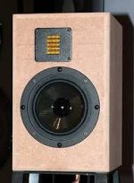
My first design is inspired by the Harbeth 40.3, hence the name. I had initially planned on making the Visaton Nimrod kit, but lack of subjective reviews made me hesitant. I built the Aviatrix MTM last month, and it sounded horrid on my desk.
Anyway, lets talk about the design:
HxWxD: 22"x12"10.5"
Material: 19mm Baltic Birch, Rear panel and bracing MDF.
Volume:~30L
Box: Dual Ported 5x20 cm or sealed (still unsure). 45 degree bevel for diffraction
Arrangement: TMW
Crossover: Active 3-way, using tinysine 7800B. Xo at 200hz (1st order electric), 2khz (2nd order LR). Replaced later with either passive XO or custom DSP & amp option. Time alignment and BSC using DSP.
Usage: Apartment Living room, mostly HT. Flexibility for bedroom type music listening in the future. Desired bass extension at least 40hz. SPL 85 dB at 3 meters. No subwoofer as that is staying in my bedroom and I don't need another 🙂.


It is a 3-way loudspeaker using the Visaton GF200, SB12CACS25-4, and SB26ADC with WG148 waveguide and adapter. I went for the SB12 because it was on sale at madisound and the SB ceramic line seems to be popular although I'm using the 4" in lieu of the 5. I plan on 3D printing a cylindrical enclosure with spherical back for the mid. About 1L of internal volume. I was able to get a pair of SB26ADCs on ebay for $80 and I snapped the GF200s from PE when I had still planned on making the Nimrod. I did a basic test by putting a sb12 and GRS RT1.0 in a carboard box and a GF200 in a second larger box (volume was only about 15L). It sounded better than my current SVS ultra bookshelves even in the ad hoc cabinet in which it was placed. MTW sounded better than TMW although that I suspect was due to the ribbon being above ear level in my test room.

Some questions I have:
Are there any glaring issues with this design based upon what I've detailed?
How do I do about designing bracing? Just put a bunch of fenestrated panels in and hope for the best?
Is there any benefit to using BB for the rear panel? A removable rear panel of MDF would allow me to iterate on the design with regards to ports/minor changes in volume. It would also be cheaper.
The WO24p-4 went on sale for almost the same price on madisound so I also snapped up a pair of those. Not sure if I should go with that instead of the GF200. Virtuixcad shows I can get much deeper extension with the WO24, but I'm not sure it matters given that it was not part of my design goal. I also have seen people say that the WO24 sounds good in midbass. Not sure how applicable that is given the low XO I'm using.
Harbeth uses rear mounted recessed drivers. I figured I could line up the acoustic center of the mid and woofer this way, without using a stepped baffle. Is this possible? How do I make a good chamfer?
I'm going to a workshop tomorrow to get the baffles and bracing CNC'd. I could get baffles for the GF200 and WO24 done for the same cost as 1 pair but that would mean wasting wood. It would also mean not having being able to test whether I prefer TMW or MTW.
Thank you for your help!

P.S. Yes, I do have a measurement mic.

Impedance less than DCR???

Although I'm a novice at cabinet design, I'm helping someone with his. The resulting SPL plot showed an odd dip around 425hz.

At first I thought there was crossover error but I had him run an SPL sweep of the woofer (in cabinet) with no crossover.
The dip was still there. I then had him run and impedance sweep. Low and behold there is a big dip in impedance at that frequency.
The impedance at that point is 2 ohms.

My question is this. How can the impedance ever drop below the DCR (5.08) of a driver (Celestion TF1225) with no crossover?

Thanks in advance.

Mike

Screenshot (372).png

Amp doesnt have sub crossover setting

As mentioned above my amplifier( harman/kardon AVR255) doesn't have a crossover setting for subwoofer (klipsch r-115sw). I have put the subwoofer crossover on the lowest setting because it doesn't cut all the frequencies above 20hz (which is the lowest). Is there any ideas on how to cut the unessesary frequencies from my sub? I have thought of something like the pasted link below. I dont know if it's a good idea since I want to keep the amplifier. If you have another idea on how to do it will be highly appreciated.

https://dbmelectronics.gr/ihos-auto...tis-entasis-proenishusis-low-pass-filtro.html

I know it's a Greek website since I come from Greece. But I guess you will be able to look at this part. I appreciate everybody's help!

Environment Noise and iPhone Camera Adapter

I had a thread earlier this year talking about a small lower power device for streaming or playback of FLAC/WMA lossless files. I wanted something small and quiet to sit under the TV.

Due to a family bereavement I didn’t go ahead at that time.

However, I was browsing recently and read about the iPhone “Camera Adapter”. This is just a short cable with the Apple connector at one end and a USB port at the other so that you can upload your SLR camera pictures to your phone.

I read that that you can also use this to connect an external DAC, so I thought this might be a useful thing to have so that I can play music without the background noise of my tower PC.

I bought an inexpensive third party one and it does indeed work perfectly, I can play Qobuz files at any quality, although the highest resolution files I have are 192Khz/24 bit (for what it’s worth!).

I hadn’t really realized how much noise even a fairly quiet PC with all the fans on the slowest speed and a few hard disks makes. It was somewhat eerie hearing no sound at all between tracks and in pauses. It was also possible to hear the tonality of instruments more clearly.

After this I am utterly convinced of the necessity for a silent playback device when my “in development” sound system eventually makes it into the lounge from my shed.

Before this I had never really thought of the iPhone as a serious music source but to some extent it clearly is. (I guess Apple always thought that!)

The only downside is that the only volume level available is 100%. Fortunately I have a preamp so I just control the volume from there.
  • Like
Reactions: stv

Vintage style console with dual MEH (design idea)

This morning I got an idea on how to smuggle a MEH based stereo system into my living room - build them into a console style cabinet to serve as a TV stand. The picture is a random one from internet - it would have to be a bit more modern looking, but I hope you get the idea.

IMG_8200.jpeg


2 x Fane Sovereign 8-225 + 1" driver in my SPL Runt clones should work well in this.

The placement would not be ideal, but ot should work. I need to try this arrangement with the separate boxes one day to find out if it is worth the effort🙂

DIY DSP DAC for Car Audio Amplifier DYNO with 6-8Vrms Output?

Hello everyone, let me know if I'm getting over myself here as I'm looking for car audio performance with DIY prices

I am wanting to build a 6-8 channel DSP which have DACs that can provide 6-8Vrms single-ended outputs. Ideally, I would like to have a USB into the DSP as the signal source, and then DACs that can sufficiently match car audio amplifier's gain. I have found the PCM5102A chips that have 2.1Vrms, which would suffice, but I'm striving for car audio relatability. Worst case, I find a used car DSP with what I'm looking for that suites my needs but that's not DIY.

Right now, I am thinking of using an USB to I2S into a Wondom ADAU1701 module for processing, then 3 or 4 PCM5102A boards for I2S DAC, and then a 5x times multiplier on each DAC? I would remove the crystal oscillator for the USB to be master board.

Let me know if I'm trying way to hard or if you have any other recommendations that I could try out

thank you

laser measurement speakers

hello everyone.
on the net you can find programs that use the laser to make measurements on the speakers. this method is considered very precise. what is your opinion on this topic?.
an example in the link below:
https://www.listeninc.com/products/...hragm-displacement-measurement-using-a-laser/
i have to make measurements to obtain the small-thiele parameters.
do you know of an open source or free program that does this?.
i think that in addition to the program and the laser source, something is needed to collect the signal and then pass it to the sound card.
i have already read the following page on this forum but i would like to know if there are other alternatives:
https://www.soundanalog.com/projects/project-one-f5w4d-6xm4j
hello and thanks.

AD1865 DAC & tube I/V kits with R-core.

Two kits available with built and tested Miro AD1865R DACs plus PCBs for tube I/V & PSU. Also custom R-core transformers to run Tube stage and DAC. I2S input.
Will include a Soviet 6N23P tube for testing, this will get you up and running and can set plate voltages and hear music.

Transformers have 130V / 6V outputs plus CT 9-0-9V for DAC and will include shunt regulators designed by Dadod. Tube holder also included

117 / 117V AC primaries for anywhere.

IMG_1004.JPG

£85 plus shipping - package will weigh around 800g so tracked shipping could be around £20


Two AD1865R DAC chips and PCBs with custom SOIC28 to DIP24 adapters designed by Prasi. Also one AD1865R UFL only PCB.


IMG_1059.JPG

Blue AD1865R PCBs with chips - £20

UFL only with chip mounted - £15


Paypal only, as friends or pay fees.

Tweeter or Compression Driver for 2 way build with Dayton 7" E180HE-44

Hi fascinated by the possibilities offered by the Dayton Epique 7" Wide Range E180HE-44 subwoofer.

Anybody got any builds that uses this in a 2 way?

Partial to a horn tweeter or waveguided tweeter.

A minimalist crossover would also be ideal.

Or is this purely for subwoofer use?

Any leads or help would be appreciated.

Thanks!

Newbie Sony TA-F170 repair help

Hi all,

I'll put some history of the amp at the bottom if you want to read that, or if it may be helpful.

I have recently fixed my dads old Dual Turntable from 1991 and I paired it up with a Sony TA-F170 amp which he used and some old mission speakers from a similar time. currently the amp works most of the time on the right channels but the left channels cut out / fade away to just a crackly noise after a very short amount of time. I have it wired with the high frequencies on the A channels and the low frequency on the B channels for each speakers so they both have two separate inputs. I am almost certain it is the amp not the speakers because if I bob the floating deck of the turntable up and down then the left speaker sometimes kicks in for a short amount of time which is I assume because it forces a surge of current because the needle has a pressure change. And I have heard both speakers play at high quality for a bit together, but it never lasts long. I also tried them with a different input (aux) and the left speaker again doesn't quite work. I have taken the amp apart to see if there is anything obviously wrong, but apart from some very slightly dodgy looking solder joints on the bottom and some brownish what looks like water but it doesn't come of and is not wet. I assume its some small corrosion but it could be a glue of some sort. Also, I don't use it with headphones so it doesn't really matter, but either the port is broken or my headphones aren't compatible. If I wiggle the speaker channel change switch, the speakers sometimes sort of cut out a little, so I think those contacts need cleaning. Sadly I don't have any contact cleaner because I am new to this sort of thing.

If there is anything you think I can do to fix this could you tell me?
sorry if this is in the wrong thread.

History:
This amp was used a lot through my dads university age and was stored in an outdoor shed when he stopped using it. Not temperature regulated but dry. Then my brother found it and used it with a radio in a different shed, still dry, but it was out and being used and not in a box at this time. I think it worked well at this point. Then he brought it inside and used it in his room. Then a couple of years ago he said there was something wrong with it and put it back in its box in the shed and brought a new cheap amp. I recently found it to use with the record player which I fixed and it sort of worked, but I see why he brought a new one. I don't want to buy a new cheap amp, because I've heard this amp work properly and it makes a great sound. At the moment I use it with just the right speaker playing (the left is plugged in it just barely works.) I also like it because it has four outputs instead of two like most amps and it has a pre-amp built in. (and I like how it looks)

Thanks so much for any advice you can give. If there isn't much I can do myself I'll take it to my local repair shop and I can tell them what you tell me to make their lives easier.

Fabian

Arcam Delta 290 - which ones are "the drivers" ?

Fellow hifi nerds,
I'm kinda sorry I joined this forum mainly to ask for help, but it's the only forum I've found on the web where knowledgeable people have in the past discussed this beautiful machine 😉.
What happened? While rearranging my room I managed to short my speaker cables (hey, haven't we all done that at some point?), resulting in a blown mains fuse. Replacement fuse blew immediately, so I decided to buy new mosfets IRFP240 (and an "audiophile" fuse 🙂). Now the amp powers up nicely, but the sound is completely distorted, maybe because there is zero idle current, unless my multimeter is lying to me. I've read up on all old threads regarding the Delta 290 but I'm afraid I'm at a loss: What exactly are those "drivers" that might be shot? Can someone point me towards the parts responsible for delivering the necessary idle current? I'd be grateful for any thoughts.

Hello, I am a maintenance technician living in Thailand. Now I have received a DENON AVR4311 with the symptom of no sound. But as far as I have checke

สวัสดีครับ ผมเป็นช่างซ่อมบำรุงที่อาศัยอยู่ในประเทศไทย ตอนนี้ผมได้รับ DENON AVR4311 ซึ่งมีอาการไม่มีเสียง แต่เท่าที่ผมตรวจสอบแล้ว จะมีเสียงเฉพาะในโหมดสเตอริโอและลำโพงด้านหน้าโดยตรง ผมลองปรับโหมดเสียงแล้ว ช่อง Center Surround ก็ไม่มีเสียง ผมตรวจสอบเวอร์ชั่นเฟิร์มแวร์แล้ว ทุกอย่างเป็นปกติ แต่ตำแหน่ง เสียง และวิดีโอแสดงเวอร์ชั่น PLD:00.00 มันหมายถึงอะไรและ PLD คืออะไร ผมไม่เข้าใจ

David L Whitehurst (dlwhitehurst) - Here to blow the dust off of my Tube amp knowledge

Hi folks. I'm 62, nearing retirement from a long IT career in Enterprise architecture and development. I've recently took the guitar out of the closet warmed up a 12AX7/EL34 tube amp that I made some time ago. I want to build another, better one, for a friend that's looking for less physical work and plays guitar. I would like to make tube amps on demand for other guitarists as a retirement gig. I need to blow the dust off of my education 40+ years ago and work with my friend to build another tube amp. My first post will be in Power Supplies, to discuss technicals around the "need" for a $100 Hammond transformer. I would think that I should determine my circuit power needs and then design a more economical solution.

Anyhow, great to be here and I can't wait getting to know the other nerds here. Funny story: when I was little my grandfather would let me destroy all these broken amps, radios, tvs, etc. with diagonal cutters, and then my grandmother would get so mad because I left all these little leads in the rug upstairs and she couldn't get them all out of the rug. I wasn't fixing anything really but I sure do relish the memories and the experience.

David L Whitehurst (dlwhitehurst)

What Solid State Amplifier can I build to suit my needs?

Hey all! I'm building a solid state amplifier with the main goal of live shows (in basements mostly). The primary speaker its driving is a Celestion G12T 75 along with a couple other smaller ones wound to get a final 4 ohm load.

My initial plan was to put something together really quick because I am in a time crunch. Particularly using a TDA7498 power amplifier as the final stage. I was planning on splitting my cabinet into 2 and running 2 separate lines to get a stereo sound. If this is a possibility I would like to build a stereo pre-amp stage. Something that has a lot of tone customization. I was thinking of even including an interchangeable tone stack (Fender/James). For a possible pre-amp stage I was thinking of using a Model Fet))) pedal design but I have doubts on how the voltage output of that would match the TDA7498.

Honestly I am down to scrap the TDA7498 if it means I can get something louder more suited for live shows.

Another idea I had was to run the signal through a common pre-amp stage then have a fx out channel which splits the signal into 2 to get a more stereo sound before going into the TDA7498.

Any ideas?

Can anybody help ID this old potted Hammond Tranny marked 92747?

Been helping a friend organize the estate of her late husband and we have come across some of these Hammond sealed transformers. Marked 92747, has 7 pins, ohm meter gets the following readings:
Pins 1--2 reads 20.6 ohms
Pins 3--4 reads 23.6 ohms
Pins 5--6 reads 1 ohm
Pins 6--7 reads 1 ohm
Pins 5--7 reades 1.8 ohms

Attachments

  • IMG_7100.JPG
    IMG_7100.JPG
    282.3 KB · Views: 13
  • IMG_7101.JPG
    IMG_7101.JPG
    283.7 KB · Views: 13

For Sale Svetlana 811-10 vacuum tubes

I have a good pair of these now hard to find vacuum tubes. I'd like to get $90 for the pair. They are packed and ready to go but in truth I have no way to test them as the 6.3 volt 4 Amp heat just does not go with any tube tester. I only have the word of a friend. So, money back if they don't hit 90% or better.

Cheers!

Attachments

  • s-l1600.png
    s-l1600.png
    901 KB · Views: 70
  • s-l400.jpg
    s-l400.jpg
    22.3 KB · Views: 65
  • s-l400-1.jpg
    s-l400-1.jpg
    34.9 KB · Views: 67

Systemdek IIX 900 modification

Hi,
I've just purchased a Systemdek IIX 900 with a 11.6mm thick, 937g weight plastic (probably acryl) platter. The springs works fine with this low weight platter.
But.
I've tried to put on a modified platter from my Rega (19.6mm thick acryl, middle turned out from from the bottom1455g) and the platter is immediately sitting on the wood body of the turntable. I've tried to adjust the 3 spring adjusting screw and I could not get a gap. Then I've turned the platter upside down (just to test, of course not usable this way) so it does not "overhang" below the sub platter and I can adjust to get about 3-4mm gap.

My plan was that I get an acryl platter turned for the Systemdek, as I saw several already with thick acryl platter on it (about 20mm). I have raw material for it, but it will not work. Are my springs damaged? Do I need to replace the springs?

I know the original Systemdek platter is 10mm glass, should weight about 1.7kg. That would probably fit with the screws about all the way in, but how do others fit the thick acryl plate on it? I do not understand that. There must be a milled/turned out part from the bottom to achieve the same record height, but then there is an "overhang" below the sub platter, which will not fit.

Just for info, I've also tried with the Rega 12mm glass, 2kg platter, I could not get a consistent gap. Near the arm the platter touch the turntable body. Barely, but it does.

Please help how to proceed. I know the thick acrly works really well on this TT, I want to have that on my recently purchased Systemdek.

Thanks!!
JG

Reading graphs help - breaking down Hificompass measurements

A know a lot of you take the measurements from HifiCompass very seriously as he is a 3rd party tester.

I am not understanding his star rating.

Lets take three drivers that are very similar and compare them. I would like you to explain what makes one better than the other.

1, Dayton Aluminum Dome Mid
https://www.parts-express.com/Dayto...nce-Aluminum-Dome-Midrange-285-020?quantity=1

HifiC review 5 stars
https://www.parts-express.com/Dayto...nce-Aluminum-Dome-Midrange-285-020?quantity=1

2. Dayton Fabric Dome mid
https://www.parts-express.com/Dayto...Fabric-Dome-Midrange-8-Ohm-285-022?quantity=1

HifiC review - only 3 stars
https://hificompass.com/en/speakers/measurements/dayton-audio/dayton-audio-rs52fn-8

3. Hivi DMB-A
https://www.parts-express.com/HiVi-DMB-A-2-Fabric-Dome-Midrange-297-716?quantity=1

HifiC Review - back up to 5 stars for this one

I will post up the 3 graphs I think I understand pretty well: the frequency response, the distortion, and the waterfall or spectral decay

Looking at these they look almost the same to me. They might have little variations but not enough to knock one of the three down to 3 starts and give the other two a flying color review.

What am I missing? If anything I'd give the Dayton Aluminum a knock for that giant peak at 12k hz. [/B]

Attachments

  • Screenshot 2024-10-20 200141.png
    Screenshot 2024-10-20 200141.png
    759.6 KB · Views: 57
  • Screenshot 2024-10-20 200107.png
    Screenshot 2024-10-20 200107.png
    466.7 KB · Views: 47
  • Screenshot 2024-10-20 200028.png
    Screenshot 2024-10-20 200028.png
    390.5 KB · Views: 49
  • Screenshot 2024-10-20 195945.png
    Screenshot 2024-10-20 195945.png
    859.9 KB · Views: 45
  • Screenshot 2024-10-20 195910.png
    Screenshot 2024-10-20 195910.png
    365.2 KB · Views: 45
  • Screenshot 2024-10-20 195832.png
    Screenshot 2024-10-20 195832.png
    553.2 KB · Views: 44
  • Screenshot 2024-10-20 195749.png
    Screenshot 2024-10-20 195749.png
    612.7 KB · Views: 45
  • Screenshot 2024-10-20 195649.png
    Screenshot 2024-10-20 195649.png
    893.6 KB · Views: 43
  • Screenshot 2024-10-20 195551.png
    Screenshot 2024-10-20 195551.png
    292.7 KB · Views: 46

Repair and Adjustment of Parasound PLD 2000 Preamplifier

Good day ! I hope that someone here in the forum has information about the adjustment of the Parasound PLD 2000 preamplifier. In the late 90's I did warranty repairs here in Germany for a company I didn't know at the time called “Parasound”. In case of major problems I could call Tony Points from the service center at Parasound and by working together I was able to repair every device. Unfortunately, I no longer have any contact with Parasound. I have also written to John Curl here in the forum. But I don't know how he is doing and if he is still active here in the forum.

I already repaired my Parasound PLD 2000 . At first I feared a fault in the "magic 4-quadrant differential amplifier". But it was a simple 10 Ohm resistor ( R073 10 Ohm ) in the power supply limiting the current on the +30 volt line that was open . ( Possibly the resistor also forms an RC low pass with the following
capacitors.) Unfortunately I only have the circuit diagram and no adjustment instructions. Important would be the quiescent current in the output stage which is measured via two 0.47 Ohm resistors. There are even adjustment points for the quiescent current on the circuit board.


Thank you very much !

Best regards from the Odenwald
Stefan Winter

A dream of youth… Crescendo Millennium Edition Amplifier

Hello everyone;
I was in the 10th grade of a technical high school in 2001 when Elektor released the Crescendo Millennium Edition Amplifier. When I saw it for the first time, I was very impressed. But it was a very expensive project for a student.

I wanted to build this amp for many years, but due to lack of time and the discontinuation of Mosfets, I was unable to do so.

I found out that @RM, who I met at Diyaudio, had mosfets for the Crescendo amp. I immediately started drawing PCBs and boxes.

I have no idea about the sound of this amp. Whether it's bad or good, I want to finish this amp, which is a dream of my youth, and have it in my collection. That's why I want to get advice from people who have already built this amp.

For example;
*What are the components that need to be matched? Is hFE matching or offset matching required for the input transistors?
*I am using OPA177 instead of OP77.

Attachments

  • cme1.jpg
    cme1.jpg
    476.2 KB · Views: 277
  • cme2.jpg
    cme2.jpg
    148.6 KB · Views: 305
  • cme3.jpg
    cme3.jpg
    148.9 KB · Views: 260
  • cme4.jpg
    cme4.jpg
    245.3 KB · Views: 209
  • cme5.jpg
    cme5.jpg
    128 KB · Views: 225
  • cme6.jpg
    cme6.jpg
    176.9 KB · Views: 219
  • cme7.jpg
    cme7.jpg
    516.6 KB · Views: 223
  • cme8.jpg
    cme8.jpg
    204.8 KB · Views: 213
  • cme9.jpg
    cme9.jpg
    323.7 KB · Views: 224
  • cme10.jpg
    cme10.jpg
    240.5 KB · Views: 228
  • cme11.jpg
    cme11.jpg
    672.4 KB · Views: 259
  • Crescendo_Millennium_en (1).pdf
    Crescendo_Millennium_en (1).pdf
    2.6 MB · Views: 207

DIY 12v trigger in amp

Hi. Building an amp intended for LCR duties with 3 NC500MP modules. Was looking to add a trigger input but also wanted the option to run the amp without trigger. In an attempt to simplify the design I got the idea if I could tie all 3 GND (J6.4) together and use VAUX (J6.1) from one amp to control PS Enable (J6.9) on all 3 modules. Would this work or would it destroy them?

Attachments

  • Messenger_creation_7CFB4FCE-60F3-4A58-A5C1-C8D4F51F3DEB.jpg
    Messenger_creation_7CFB4FCE-60F3-4A58-A5C1-C8D4F51F3DEB.jpg
    96.5 KB · Views: 83
  • Messenger_creation_BAB74F08-A749-4F2C-9B3C-FCCB35BD5BE2.jpg
    Messenger_creation_BAB74F08-A749-4F2C-9B3C-FCCB35BD5BE2.jpg
    158.8 KB · Views: 81

EOSC10Kv3 - LT AN67 10kHz oscillator : new updated version !

Hello all,

Some years ago now, i showed to DIYers in this forum my own build of the
AN67 LinearTech application note high performance ultra-pure sine oscillator.
I used it to check the performance of my EADCAKMv1 ADC project (based on AK5394A).

Many DIYers were interested to get the PC to build it, and so i decided to organize
some group buy to sale this PCB.
Now, i continue to receive request to provide the bare board of this oscillator regularly.
The concern is that the LT1230 become hard to find, or, at prohibitive price.

Thus, i decided to update the design of the oscillator, replacing LT1230
by the easy to find LT1229 and using SMD parts.

Some improvements listed below has been done :

-
  • Much smaller PCB size, mainly SMD parts.
  • SPDT toggle switch for power on/off on the front of the PCB.
  • Ultra low noise regulators option (LT1761/LT1964)
    or standard regulators (LM317L/LM337L).
  • Output voltage adjustment on front panel from 500mV to 3Vrms.
  • Can be supplied with 4x6F22 battery’s.
  • Reverse polarity protected.
  • Improved low stray capacitance design
  • No HF oscillation output behaviour with long coax cable
  • Solid ground plane with minimum slot on bottom side.
  • Oscillator section use MMA0204 precision low noise
    thin film melf resistor and ECHU stacked metallised PPS capacitors)
  • Fit in low cost Hammond extruded aluminium enclosure.

I have received the prototype PCB last week, it look like this :

The PCB dimensions are 92x75mm, intended to fit in the small
aluminium enclosure (1455J1201 from Hammond).

EOSC10KV3_PCB05.jpg


After some painstaking soldering work (i like that!), it give a fully populated PCB :

EOSC10KV3_PCB04.jpg


In the Hammond enclosure ..

EOSC10KV3_box05.jpg


EOSC10KV3_box10.jpg


EOSC10KV3_box11.jpg


Of course, now the important thing to do is to test it's real performance !
Measuring a THD below ppm level with some confidence is an hard task.
Many parameters can corrupt results.
So, much care has to be done before choosing measurements method.


The measurement below, show the FFT result of the oscillator output
connected to my EADCAKMv1 ADC through a passive stepped attenuator.
The attenuator was set to -10dB attenuation to find the lowest thd point
of the ADC. (the measured THD come mainly from the ADC itself).
The EOSC10KV3 board is set to 1Vrms at output (single ended).
It is supplied by a +/-16dc linear PSU (Metrix lab PSU).

Photo spectrum
EOSC10KV3_spectrum.jpg


As you can see the spectrum plot is very clean, with all spurious much below -120dBV
and noise floor below -140dBV in the full measured bandwidth.
Here, and without notch filter, the measured THD is 0.00006% (-124.4dBc) !
So, we can assume with confidence that oscillator THD level is then much low this level,
because we reach here probably the lower thd available with any ADC IC !
That confirm the fact (confirmed by JensH and others here) that the AK5394A
is still the best audio ADC available...
(The full test setup is described in spectrum plot)


To finish it, i have to mount the circuit board in it's enclosure.
I will drill it these days.
(all test has been done at free air without enclosure).
I will add pictures with finished design soon.

As my others project, i have done some documents for this updated design,
in order to simplify as much as possible the building task and get a
working oscillator "fingers in the nose".

You can download below the schematics and full bill of material in pdf form :

A good new, now with it's reduced size, the bare PCB price is seriously falling.
Overall BOM cost has been also reduced and all parts are easy to find and
can be ordered using only Mouser and Farnell (or Digikey).


The new PCB price is 18€ outside EU and 17€ inside EU.
The price include shipping, Paypal fees and the complete design folder.
Of course, any DIYers interested to get the PCB can send me PM.
Regards.


Frex
  • Like
Reactions: gerrittube

Technics SU-V2 STK8040 Replace with STK8050?

Hey all!

I was wondering if someone can help with some advice replacing the STK8040 ICs in the Technics SU-V2 amp. I have found a few sources that say the STK8050 is a drop in replacement. Is this correct?

I'm working on this amp so I can gift it to my Dad for his birthday. He used to have an identical amp 20 years ago and I think he misses it, so I got another one that promptly burnt out R616. I've checked everything downstream from this and the transistors and caps both checked out, but I had some 3.3uF caps on hand so they were replaced and they should be good.

From the testing I've done I suspect the associated STK8040 has died, though hopefully I will confirm this tomorrow for sure.

Voltages seem within spec approximately 41v +/-.

I'm usually more at home repairing vintage computers so, amps are slightly new territory for me, though I've repaired the odd one before. This SUV2 is a bit more sophisticated than I have dealt with previously.

If i can obtain an STK8050 can I just swap that in and be good to go? I cant seem to find any datasheets for these ICs. Alternatively I might build a couple of replacement boards ive found on these forums!

Any help appreciated!

babylonjs and lots of particles

Not very acoustically real yet ...

I made a small room with 1 million particles emitted from from a sphere and then bounce around.
It should use WebGL2/WebGPU if you have supported gpu and browser.
Press space bar to start the explosion. 20fps on my 2017 iMac.
Very pretty to watch.

https://playground.babylonjs.com/#K0DAW0#3

Next step is to assign each particle a texture.
In webgpu have RGBA textures that we can use for storing particle data.

For instance,

r for particle frequency
g for particle SPL
b for phase value
a ...

It would be easy to multi texture allowing us encode more data into each particle should we wish to track any other metrics.


1730166947007.png
  • Like
Reactions: AllenB

Best 6BM8 Tubes

Although not a common amp tube I tested about every 6BM8 available and two stand out from the rest. Amp is modified and upgraded Pioner SX-34. Killer amp after upgrades and rebuild. The Siemens 6BM8 are second place and just a 'hair width; away from best EI 6BM8. EI projects a little further into the room with slighter brighter high frequencies. Hope this helps.
  • Like
Reactions: Sir Percival

Types of acoustic boxes

Hello everyone, I come here today to try to resolve a question that I have had for a long time, and I can't find the answer anywhere.

The question is, if there is any type of software that can represent the frequency response of a speaker, but theoretically, but not only that, because if we talk about that, we find software like WinISD, which is quite good, but I I mean, go a little further.... What I say is, a software that one can enter a 3D model of an acoustic box, and then the parameters of the woofer or woofers, and other things to add, and that the software I'll tell you what frequency response that speaker should have with that woofer in practice.

Perhaps inserting a 3D model, and having it calculated is a bit far-fetched, but perhaps one that gives more options for box types, such as for 6th order bandpass variants, or 5th order, or even 8th order.

At least I started to have this doubt because of the very interesting videos of HexiBass and its crazy designs. And also from a section of Loudspeaker Design CookBook, where it shows the different frequency responses of different speakers, but not because of their volume, or if they are bass reflex, or bandpass, no, but only because of their shape.

Some being spherical, others oval, others cubic, parallelepipeds, cylinders, etc. And by simply changing the shape, I could obtain responses of completely different frequencies, which is why it caught my attention. If anyone knows about the subject, I would greatly appreciate it if you would comment on this thread, and help me, and many who surely have this same question.

Best Electrolytic Caps for Non-Polarized (nonpolar/bi-polar/bipolar) Applications

Best Electrolytic Caps for Non-Polarized (nonpolar/non-polar/bi-polar/bipolar) Applications (particularly coupling Capacitors) in Solid State Pre- and POWER-Amplifiers

In an environment for the actually use of non polar (resp. non polarized or bi-polar/bipolar) capacitors are mostly to find polarized electrolytic capacitors.
The best known examples are any signal- and NFB- pad of amplifier stages with balanced voltages from its power supply ( +/GND/- )

The main reason therefore is the too small space in most cases.

I have often read, that by use of the reverse-mode the operating voltage of each polarized electrolytic capacitor is always between 500mV and 1V (independend of the actually maximum operating voltage value, that is to read on the capacitor).
Obviously this is right, because I haven't find very often damaged capacitors at such places.

In cases, where the capacity is 5uF or below, it is possible to perform a replace by a foil version (eliminates in any cases the cracking of the potentiometer for volume control).
But what is the best solution, if there is a capacitor between 47uF and 470uF (e. g. in the NFB loop) ?

Until know I use at least 63V capacitors and introduce an additional foil cap (arround 0,47uF until 4,7uF) for operate in parallel mode (bypass).

By any few commercial products there is additional a diode (e. g. 1N4007) in use to limit the voltage in the reverse mode. But maybe there are other important steps necessary.

The main question is, which polarized electrolytic capacitor brand should I prefer for this special application ?

Thank you very much for your advices.

These topics I have found related to bipolar capacitors, unfortunately without helpful hints.

Standard electrolytic or bi-polar?
Coupling Capacitors - Bipolar or Polarised?
non-polarised electrolytics
polarized vs non polarized cap!
Bipolar electrolytics
Conflicting information on nonpolar electrolytic capacitor use
Non Polar Capacitors
Can I make a Non-Polar Electrolytic using two polar ones
non-polar/bi-polar...same?
Polar electro with bypass cap to replace nonpolar as coupling cap?
FS: Black Gate "F" and "Nonpolar" caps
nonpolar capacitors
bi polar capacitor
Can I use polarized capacitors instead of non-polarized caps?
Non polarized Caps
Polarized cap or non polarized? TSE.

Anybody ever modify PSB Image 2Bs? Worth it? What did you do?

I'm looking at maybe purchasing a set of PSB Image 2Bs for a small system (20 WPC) I have at my cabin. From what I've read, they were decent speakers for the money. I don't intend to use a sub with them.

I'm wondering if anyone here has tweaked/modified a set of these, what they did and what results they got.

One thing that could be done is replacing the tweeters with these: Peerless by Tymphany BC25SC08-04 1" Silk Dome Neodymium Tweeter

Another thing might be to re-cap them. Which caps have people tried in a pair of these speakers? Noticeable improvement?

Of course, there's dampening and bracing too.

Phase & timing

Ok, you had positioned your woofer forward of the 'dome' tweeter on a baffle thicker than the tweeter baffle... Time alignment was the goal, and you found the crossover was easier to implement. Then your next project is a speaker with a horn mounted hi-freq. driver the mouth of the horn is flush with the baffle that the woofer is mounted, would this be considered time alignment as well? Where does the sound of a horn loaded hi-freq. system emanate from?

Anthem Integrated 2 Mods

Hi community....haven't posted here for some time. I haven't been building for awhile but have been buying and trying gear. Despite several reviews of a recessed soundstage, I recently I bought an Anthem Integrated 2. The power rating, damping factor, low level detail is all great but it needs some voicing.

I was told by the designer, mods were possible but too expensive for me.

To make the amp more forward sounding is the goal. Right now the instruments and voices mostly hover behind my speakers.

Would swapping coupling caps do anything?

Ultra-Rare Marantz Model M2 Bookshelf - Original/Suitable Replacement Bass Drivers Wanted

Hello,

i recently acquired a pair of extremely rare Marantz Model M2 'Focused Field' bookshelf speakers and would like to replace the 6.5" bass drivers as the ones they came with are very cheap replacements and the originals are basically impossible to find.

i am a neophyte so please bear with me, and i have attached all i could find after much searching. i hope to gift these to an ailing friend and realize there are some variables to consider, but i am not familiar with the calculations and time is of the essence in this case. i did find something within my budget and, assuming i needed 4ohm drivers, wondered if they might be suitable or if anyone could recommend something better:

6.5" Replacement Speaker Woofer Part # W-6024
  • Steel Frame
  • Poly Mica Cone, Rubber Surround, Vented, Bumped Backplate
  • Size: 6.5"
  • Hole cut-out: 5.625"
  • Depth: 3.25"
  • Voice Coil: 1.5"
  • Magnet: 20 oz
  • Impedance: 4 ohms, Re: 3.6 ohms
  • Power: 90 watts RMS, 170 watts max
  • Response: 29-4800 Hz
  • Sensitivity: 85 dB, 1 watt, 1 meter
  • Le: .40 mH, Fs: 58 Hz, Vas: .42 cu. ft., Qms: 3.05, Qes: .71, Qts: .57, Xmax: 4mm

Anyway, any suggestions would be greatly appreciated.
Cheers.

Attachments

  • M2 Service Manual.P1.JPG
    M2 Service Manual.P1.JPG
    109.7 KB · Views: 174
  • M2 Service Manual.P2.JPG
    M2 Service Manual.P2.JPG
    147.6 KB · Views: 152

How insertion loss of an Output Transformer is measured?

Hi guys, I always wondered how the insertion loss of an output transformer is measured by the manufacturers.
Based on definition insertion loss of any network is the power which is lost when it is inserted in the signal chain; so based on that, we should measure OPT's insertion loss by applying a sine wave (lets say 1KHz - 100V) to the primary and measure the secondary voltage one time without load and one time with the nominal load, and then divide the unloaded voltage by the loaded voltage and calculate it in dBs, am I correct?
BTW I found in some books that the formula is such this:
Insertion Loss = 20 * log (V unloaded/ V loaded),
And in some other place the formula is like this:
Insertion Loss = 10 * log (V unloaded/ V loaded)
So what do you think about it? Which one of these two formulas can be correct?
My measurement setup is like this:
IMG_20241028_175332.jpg


Assume the DUT is a 5K to 8 ohms OPT for UL 6L6 single ended amp; with the load on primary side disconnected I adjusted 4.04V on the secondary side and I get 100V on the primary; after that with the nominal Zp connected to primary I get 100V on the primary side again by applying 4.26V on the secondary side. So how I calculate insertion loss for this transformer?

Any help would be appreciated.

TPA6120 Kit Mod Composite

Hi fellow experimenters.
This simple project unexpectedly turned into an educational experience for me, so why don't I share some of it.

I bought this amp as a kit from Ebay (the build photo below) as it looked inviting to be rewired into a composite which I wanted to make one day. Very good examples can be found here on DIYA and elsewhere. Design of the kit however included questionable approaches and was lacking such critical things as rail decoupling for opamps and the TPA6120. Those had to be added, along with an easy mod turning the supply filtering into CRC, adding input RFI filter and some other. The board is also wired so that only FET input opamps are suitable. My kit came with TL071 which I used for initial tests and then changed to OPA1641. The two areas where I experimented most were:
  • Ferrite beads in parallel with the output 10 Ω resistors as I wanted to reduce the output impedance;
  • Stability & capacitive load isolation.
They are of course interrelated. Here is the schematic of my amp:
TPA6120A2_COMPOSITE3.png


The legendary NwAvGuy showed his use of ferrite beads across the TPA6120 mandatory output 10 Ω resistor and measured increased distortion. But that was more that 10 years ago and he had used beads for power lines. I figured that manufacturing of ferrite mixes for beads for signal lines may have progressed since then and picked Murata beads NFZ2MSD131SN10 which they specify for audio signal lines with reduced THD compared to beads for power lines. HD is not the whole story of course when it comes to ferrites. I have read Purifi blog posts on the subject of hysteresis distortion in ferro-magnetic cores and a glimpse of what it takes to design feedback to conquer that. Such sophistication is beyond my ability but reduction of output impedance still seemed a worthwhile goal. So I set out to try and measure the ill effects if I could. At least I would know not to do it any more 😉. Air cores were out of question due to the very tight space on the board.

This study showed one possible THD measurement set up and striking results (30 dB difference!) that I thought I would be able to replicate even with my modest tool - the old horse EMU0404. Not so. My measurements of THD before the bead (TP1 on the schematic - feedback take off point) and after it (TP2 - the output) showed no meaningful difference at any frequency or signal level always hitting soundcard loopback measurement floor. Which is just to say I was not able to detect it not that there wasn't any. Standard SMPTE IMD measurement did not reveal any difference either.
Evidence of increased distortion in the bead emerged with CCIF IMD measurements. Even though the measured IMD levels were quite low (below -95 dB) there was consistency of lower IMD at TP1 at different signal levels. A couple of dB but nevertheless. The largest IMD difference between TP1 and TP2 I managed to detect was 5.5 dB in favor of TP1 (see graphs below). But hey, isn't it so that such difference is present also with air core inductors if the Q damping resistor is placed inside? I have not researched that but someone must have measured contribution to THD/IMD of the aircore coils with resistor inside.
1.png

Not being particularly keen on absolutely lowest THD numbers I am happy with what I've got - output impedance of ca. 0.5 Ω and hardly any (audible) HD. The only thing bothering me is the hysteresis distortion and whether I would be able to hear it some day. On the other hand, I guess most phones (and iphones) have a bead in their audio chain so I may have been already numbed by the beads' sound... But maybe qualities of ferrite mixes have really evolved enough and beads are not so objectionable any more? Are there other experiences/measurements around? I hope I have not sparked a general ferrite discussion🙂.

Stability.
Early on I had decided that gain of 2x would be plenty enough for this amp. I also wanted to retain the loop gain as high as I could at 20 kHz. TINA-TI suggested that the circuit (with modest speed opamps) might work even without additional compensation (phase margin a tad above 30° @ unity gain cross-over at 7 MHz, gain margin 8 dB). May be ok, but from what I have learned so far it felt marginal. I ended up with a simple but crude solution of C3 + Rg2.1 shunting opamp input from 1 MHz onwards. Key drawback - loop gain (and bandwidth) varies with the volume pot position since the opamp input is not buffered. For example, -3 dB upper bandwidth varies between ca. 400 kHz and 640 kHz with the lowest being at about mid position of the pot viper. I understand why rather intuitively but could not calculate it unfortunately.

Not perfect, but I can live with the mentioned effects since gain magnitude variation in the audio band stays below 0.01 dB at all pot positions, loop gain at 20 kHz is 54.5 dB at all pot positions while stability margins remain satisfactory - at unity gain cross over frequency varying between 2.75 and 3.5 MHz, PM is no less that 53° and GM no less than 17.8 dB. Tell me please if you see other drawbacks or potential risks in the chosen solution that I have overlooked.
Here the plots with pot at full volume:
Bandwidth and phase response.png


Finally, back to ferrite beads in the output with respect to capacitive load isolation. TPA6120 datasheet recommends output resistor (R5 in my schematic) to be at least 10 Ω to ensure stability. However, if a ferrite bead is added in parallel I found that it is beneficial to reduce the value of R5 because 10 Ω is not dumping enough the inductance of the bead to lower its resonant ringing with capacitive loads. Topping L30 has allegedly used 3.3 Ω (without any bead/inductor though) however they managed to include the resistor in the GNFB and had added a zobel. The 3.3 Ω value concurred with my simulator as the lowest permissible before oscillations would begin on fast transients even with small capacitive loads. I stopped at 4.7 Ω. Experimentally, I found that another dumping resistor R6 of 0.5 Ω in series with the bead is good to have. Not strictly necessary but it decreased the ringing further on higher capacitive loads. Here come scope shots with 10 kHz squarewave into 33 Ω load resistor in parallel with capacitors from 0 to 100 nF. It is very stretched IMO, I consider anything above 10 nF being rather unlikely in the headphones' world, but I will readily admit my ignorance here. As with IMD measurements, TP1 shows capture before the bead, TP2 - after. All measurements here without the input RFI blocking capacitor C1.
2.png

For the sake of experiment only here is also a 10 kHz squarewave with 1 μF load - a highly improbable case. Wave form on the right side shows wild (but well damped) ringing in case of insufficient damping R5 = 10 Ω and R6 = 0. The loop remains stable although TP1 wave form is looking ugly. The bead does its isolation job well!
3.png


The build photo where the original Ebay kit can still be recognized 😉 :
Untitled design.png


Happy experimenting to all!
  • Like
Reactions: robjordan

Denon DCD-660 Disc Not Reading Following Belt Change

Hi All,

I am currently attempting to fix my DenonDCD-660 cd player. The main problem was the disc tray was struggling to open. I replaced the belt associated with this, and this issue is fixed. However, now the CD is not turning or reading when the disc tray is closed. I have cleaned the laser, but to no avail. Any thoughts on why the CD is now not reading and how to go about fixing this? It was reading previously, so feel like a major fix shouldn't be required?

Record Speaker Line Out on a PC/Laptop/RaspberryPi or ESP32

Hello diyAudio family,

I am looking for a readily available circuit or a DIY solution where I have a speaker, I want to remove the speaker and convert this speaker into a audio line input so that any PC, laptop, Raspberry Pi or a ESP32 can consider it as a audio input and I can record the audio signal. Any help or starting point for this project would be appreciated.

  • Locked
Fancy Interconnects? How about a potato, or even mud?

OK, we've all heard or read the sales pitch for interconnects of fancy materials and geometries, I've got them all beat.

Did you know that you can pass a line level audio signal thru a banana? How about a sweet potato or even a bucket of mud? You can, quite easily. No joke, it really works. You can even stick two wires in the dirt in the back garden and pass an audio signal thru the dirt.

I spent this afternoon doing just that, and making recordings of it. This is no April Fool joke, it really works. If any of you are interested in what it sounds like, you can do it yourself, or I can post samples here.

You'd be surprised at what a musical signal sent thru a banana, a potato or a bucket of mud sounds like. Cyro that, cable guys! 😀

Anyone care to hear it? Anyone care to guess what it sounds like?

Resistor power dissipation

Hi all,
I'd like to know if maximum power dissipation of a resistor sums up if using multiple resistors in parallel as opposed to a single higher powered resistor? Granted we use the same values for all the resistors that are connected in parallel.

Let's say we tie a pair of 5W 10k resistors together for a total of 5k, do we end up with the same heat/power dissipation of a 10W resistor, or is the 10W going to run cooler by having a larger body and probably a different gauge wire inside it?

First time with a question on Third-order crossover

Is there any calculator or formula for reverse calculating results of “third-order” crossover such as crossover frequency and Q-factor from component values?

In second-order crossover, there are two formulas which are resonance (f = 1/(2 x Pi x sqrt(L x C)) and Q-factor (Q = sqrt(R^2 x L/C)) formulas so that we can definitely reverse calculating crossover frequency and Q from any given L and C values.

How about third-order crossovers?

Please do not suggest me to go using Xsim or VituixCAD because I’d like to know the simple and quick methods to approximately estimate the circuit.

Luxman L-550 AX voltage change 100v to 120v

I have a Luxman L550AX that is a Japanese spec 100v version. I am using an external transformer but I want to move the internal jumpers to set it up for 120v 60hz.

I opened it up expecting to see something like the first picture (A Musical Fidelity piece that I am working on) where I can just move the jumper.

But then I opened the Chassis, it is much more crowded and the power inlet has no easily accessible jumpers. It looks like the power supply is under the grey shield marked in the picture.

Does anyone know how to change the input voltage on a Luxman L-550 AX? I am assuming that it is a simple jumper change and that the jumpers are located below the grey shield, but I do not have a schematic and I don't want to take this apart if I don't know what I have to change ahead of time.

Attachments

  • IMG_3197.JPG
    IMG_3197.JPG
    174.3 KB · Views: 550
  • IMG_3196 - Copy.JPG
    IMG_3196 - Copy.JPG
    300.9 KB · Views: 628

Setting up a Fusion Amp 3-way Step-by-Step

Hello people!
It seems that many people are having trouble getting a Hypex FusionAmp set up properly. Others simply would like a clear application note.
As I did not seem to have had any issues with my method, I will share here what I did in a step-by-step instruction as an application note for a 3-way setup!

First off, I have nothing to do with Hypex. I do not know anything other than what can be found in the HFD help file or on their webpage. As such, this is no official guide, so use at your own risk! 🙂

Before we get started. Here are some useful links:
HFD software:
https://www.diyclassd.com/img/upload/doc/software/hfd/Software/HFD_4.8.zip
HFD manual:
https://www.diyclassd.com/img/upload/doc/software/hfd/Documentation/HFD_4.8_Help.pdf
FusionAmp manual:
https://www.diyclassd.com/img/upload/doc/plate_amp/FusionManual.pdf
NC100HF datasheet:
https://www.hypex.nl/img/upload/doc/ncore_mp/nc100hf/Documentation/NC100HF_03xx.pdf
NC122MP datasheet:
https://www.hypex.nl/img/upload/doc/ncore_mp/nc122mp/Documentation/NC122MP_02xx.pdf
NC252MP datasheet:
https://www.hypex.nl/img/upload/doc/ncore_mp/nc252mp/Documentation/NC252MP_02xx.pdf


The way I used my FA123 is for a classic three-way setup. My gain values and delay values are most likely very different from yours as I use a midrange driver that is significantly more efficient than my tweeter and I use side firing ineffective subwoofers sitting far behind my mid and tweeter. This is however, one of the odd combinations that is possible with a DSP plate amp as the Fusion series!!! 😀
Fore more info on my build see this thread: Small active 3-way floor stander with a punch

I have a Yamaha Bluetooth receiver with a digital S/PDIF output. This is connected to the S/PDIF input on the master module. My TV is connected to the optical input. If I want high-resolution music, I connect my PC to the TV via HDMI which then sends it to the FusionAmp over the optical connection. For background music, I use the Bluetooth receiver via phone or PC.
I use the auto off and signal detection functions. In firmware version 1.3, these work great. I connect my PC to the TV or Bluetooth and start playing music and in roughly 6 seconds, I have music. In that time the module wakes up and select the input that is used.
Very girlfriend friendly 😛

The following posts will be a step-by-step guide on how I setup my FusionAmp and designed a crossover with it. It may not be the one and only way, but it works 🙂


Text underlined like this are steps you have to take.
The rest is just information and explanation like this.

Hifi Selbstbau DK-SAT 1 kit

For sale monitor kit speaker kit from HiFi Selbstbau Germany with Eton Bassmid and Harwood AM-20 airmotion tweeter.I have all the dokumention to build the enlosure and schematic for crossover.I also have all parts for crossover if someone will to buy this.There are Jantzen SuperiorZ caps,Mundorf copper foil coils,intertechnik air coils and Jantzen superes resistors.Price only for 2x eton 5-880 bassmid and Harwood AM20 air-motion tweeter is 150 euro plus shipping,with all crossover parts included is 250 euro plus shipping.

Attachments

  • 20241019_142357.jpg
    20241019_142357.jpg
    587 KB · Views: 116
  • prenos (5).jpeg
    prenos (5).jpeg
    7.6 KB · Views: 105
  • prenos (4).jpeg
    prenos (4).jpeg
    8 KB · Views: 103
  • 20241019_143207.jpg
    20241019_143207.jpg
    722.2 KB · Views: 104
  • 20241019_143158.jpg
    20241019_143158.jpg
    749.9 KB · Views: 97

Kemet capacitors

Some verry good caps lije new condition,some are unused some are used for only a month or so.Plese look on picture for data.Price for lot is 150 euro including shipping inside EU!This are big and havy caps verry good for class A current amps,becouse this caps can handle lot of amps.More info on contact.

Attachments

  • 20240428_203152.jpg
    20240428_203152.jpg
    546.5 KB · Views: 468
  • 20240428_203156.jpg
    20240428_203156.jpg
    444.5 KB · Views: 450
  • 20240428_203200.jpg
    20240428_203200.jpg
    413.9 KB · Views: 382
  • 20240428_203204.jpg
    20240428_203204.jpg
    550.2 KB · Views: 364
  • 20240428_203213.jpg
    20240428_203213.jpg
    449.5 KB · Views: 452

Lining a Eland cabinet for an Alpair 10.3

I am gearing up to build a two ELAND cabinets using MarkAudio Alpair 10.3 drivers (already purchased).
My question regards lining ("lagging") the cabinet with Ultratouch insulation.

The first schematic from DIYaudio states and shows that all surfaces should lined
https://www.diyaudio.com/community/...audio-fostex-tb-dayton-seas-etc.323051/page-3

While the schematic posted on MarkAudio.com states and shows that one of the sides should NOT be lined.
https://www.markaudio.com/eland-alpair-10-3-compact-mltl/

The first depiction is attributed to Scott and the second is not (or forgotten). Otherwise the dimensions appear similar. So my question is obvious, do I line all surfaces or not?

Before someone responds: "try it both ways ....", the manner construction does not allow for a removable back in order to "experiment".

Thanks, -Tom

Accessing Pot to Clean on Cambridge A&R A60

Looking to thoroughly clean a slightly noisy pot on the cambridge A&R A60. I have been using contact cleaner and trying to put it down the small holes in the casing, but don't, think it is penetrating deep enough. To access the Volume pot and give it a thorough clean, do i need to just remove these circular metal casings, using small pliers to bend back the metal attachments? Please see the photo for reference. Thanks!!

Attachments

  • IMG_3787.jpg
    IMG_3787.jpg
    425.3 KB · Views: 38

PCBs for Samuel Groner's Low Noise Laboratory Grade Measurement Amplifier

UPDATE: all board have been sold. Thank you!

For sale are PCBs for Samuel Groner's Low Noise Laboratory Grade Measurement Amplifier as published in the Linear Audio Vol.3.

Quoting the author:
"[The preamplifier] is particularly aimed at noise measurement tasks. Its design features a single-ended JFET input stage, an active drain load for good power supply rejection and a novel input AC coupling network which attains, together with a DC servo, a second-order response. The achieved performance includes an equivalent input voltage noise density of 390 pV/rtHz (1 kHz) and 500 pV/rtHz (10 Hz), a frequency response of ±0.1 dB (10 Hz–100 kHz), a power supply rejection of at least 95 dB (10 Hz–100 kHz) and a quiescent current of just 17 mA. Detailed theoretical background on low noise design along with concise construction and application notes are included [in the article].

Samuel has kindly made gerber files for the board available on his website, and I ordered a board for myself. However, there was a minimum batch, so I am offering here the surplus boards.

The BOM can be found at Samuel's web site. Should you need the schematic, I'd recommend buying Samuel's article from Linear Audio - it is only EUR 2.99 and is immediately downloadable.

I am asking for $30 per board with free USPS First Class shipping to the continental U.S. For the rest of the world, add $12 for shipping. Payments via PayPal.

Please PM me if interested.

Attachments

  • Measurement Amplifier.JPG
    Measurement Amplifier.JPG
    91.4 KB · Views: 904

For Sale Genalex Gold Lion 6922/E88CC Tubes

I bought these tubes recently for some tube rolling

Fantastic little tubes, but unfortunately due to high frequency damage to my ears, I have to sell them on.

Been used for approx 170 hours (150 hours burn in and then some listening)

These are a matched pair

UK sale only price is £105, eBay link is below for safe purchase or pick up from Glasgow (UK)

https://www.ebay.co.uk/itm/267042124795

Attachments

  • gen1.jpg
    gen1.jpg
    73 KB · Views: 52
  • gen2.jpg
    gen2.jpg
    64 KB · Views: 48
  • gen3.jpg
    gen3.jpg
    80.9 KB · Views: 47
  • gen4.jpg
    gen4.jpg
    90.1 KB · Views: 45

Tube Hoarder Coming out of The Closet.

I am relatively new to the hobby. My son took up guitar, so I've finally had a chance to start messing with tubes. I've completed a 6G2 princeton, and am troubleshooting my latest 6G16 Vibroverb build. I also have a very original Sherwood 8000 MkIV that at the very least will require a recap?

Thanks in advance for the knowledge alreay shared here, and for the willingness to help out Newbs.

- Murray

DIY portable bluetooth speaker

Hi All!

After spending a lot of time trying to choose which bluetooth speaker to buy, I got the idea that they were very overpriced, so I decided to build my own. I've never done a project like this before, so I'm a complete novice at it, but I like the idea of building my own speaker. At the moment I have the following plan:
Speakers:
Dayton Audio RS125-4 (5 inch , 30W, 65-5,400Hz)
Dayton Audio DC28F-4 (1 inch, 40W, 3,000-20,000Hz)
Crossover: Dayton Audio XO2W-2,5K
Amplifier: Sure Electronics AA-JA31213 1 x 60 Watt Class D (I'm least sure about this choice because this amp has 24V in its specification, but there is for example a TPA3116D 2x50W that operates between 5-24V)

I plan to mount these in an 18mm MDF enclosure of approximately 300x200x250mm with a 50mm diameter bass reflex tube.
What do you think so far about this setup?
How do I exactly tune the enclosure dimensions and how does this match the length of the reflex tube?
What battery is needed for this setup?

Thank You!

Bluesound Powernode N180 PSU failure

Dear Forum,

Trying to repair a Powernode N180 with power failure. This is an early generation (second?) of the Bluesound Powernode.

The problem manifests itself by the infamous “red Play/Pause” button. This version has a combined PSU/pre amplifier board.
I have replaced most (large) electrolytic capacitors in the PSU, as these were “bulged”, completely dried out and no capacitance at all.
After the repair and switch on, strangely a small capacitor blew up on the Hypex NC102 power amplifier board. After that all elco’s on the NC102 were also replaced.

At present the Powernode is mostly working again: staring up normally, can be seen from the BluSound app, music can be streamed and headphone output working.
Only the NC102 power is not working. It appeared that +/- 42V power is missing.

It is very hard to debug this failure, as traces on the PSU board cannot be traced on the PSU board. Probably an active element in the switched power supply has failed.

Can someone help me with a schematic diagram of the Bluesound Powernode N180?

(if copyright issues prohibit this, please send me a DM).

Many thanks in advance,
Martin Deisting
The Netherlands (proud Home of Hypex!)

Troels Gravesen Illumina 66 Build Log

Thought I would share this here, posted elsewhere before, nearing completion now.

I had the tweeters laying around, so I figured I would go for these.
I am using a simplified geometry to make build easier, but keeping angled parts to eliminate standing waves. I modeled it in Solidworks so I could calculate internal volume with all bracing in place (have not done bracing yet). Here is the basic geometry:
index.php


Next step, build a little scale model section to make sure everything is going together well, I dont have that much woodworking experience.
6lkFWi2.jpg


So far so good, time to get the wood, got nice sheet of MDF
Y7K0YLQ.jpg


A few other notes on the build

I am using double thick front panel for rigidity.

Also, these speakers are very very similar to YG acoustics Carmel 2.
The tweeters all almost the same - YG uses scanspeak tweeters custom made for them, with I believe a slight difference.
The woofers are also very similar: Same size, same basket and motor structure. Only difference I see is YG makes machined aluminum cones that they send to scanspeak to be used, while the regular scanspeak drivers use pressed aluminum cones.
Other differences, the waveguide built into the YG speakers, crossover differences, YG have an internal resonation chamber instead of a port to outside, and of course, the YG cabinets are machined aluminum.


Front baffle going well, tweeter flush mount looking all good. I was a bit concerned, never built speakers before, or did a flush mount, but it seems to all be going well.
4D4OUg3.jpg


And woofer hole cut as well, ordering woofers now to test fitment
index.php


Woofers arrived
index.php


Sexy magnet structure
index.php


Test mounted, starting to look like a speaker
index.php

Regulators right beside OPamps pins

G'day Guys,

I am currently designing a PCB for a fairly bog standard phono stage based on the NE5532. Nothing fancy or important here.

The typical way I would handle the power supply would be something like some 7815/7915 regulators on an off board power supply pcb.

Is there a good reason not to put the 7815/7915 regulators right beside the OPamps power supply pins?

Is there a technical reason not to do this?
I can think of cost reasons but it seems to me like putting the regulator right beside the OPamp with the regulator output cap functioning as the OPamp decoupling cap to be superior.

Comments and analysis needed on the new crossover modification

I've modified my beloved commercial speakers; Braun LS200. In fact, these speakers sound decent, at least to me, and they received many positive reviews. But that was about 40 years ago--in the 80s era. If compared to nowadays speakers, they aren't perfect speakers though. They have a lot of cabinet talk. I solved this problem by try reducing mid-bass output from the dual 10" woofers. It was achieved by reducing Q of the woofers' low-pass to allow amplifier to provide more control to the woofers. Then, a slight EQ on the upper high region was added, by means of increasing Q of the low-pass of the 2" dome midrange to gain a couple of SPL there. Finally, the mid-high region was too strong as a result of midrange's mod. Hence, I decrease some duty of tweeters by raising their cut-off frequency a bit. All of these were done with extensively use of simulations on VituixCAD.

For technical detail:
Woofer - the 100uF capacitor was replaced with a lower capacitance of 68uF to lowering mid-bass output and gained lower Q at the same time.
Midrange - the 33uF capacitor on the high-pass section was replaced with lower capacitance of 22uF to flatten frequency response curve that was risen due to the woofers' midrange reproduction. And The 14.7uF capacitor on the low-pass section was replaced with 22uF too to produce more mid-high region for personal preference.
Tweeter - there was an overlap at mid-high region as a result of midrange's mod, the solution was to reduce some duty of tweeter's operating range. Consequently, the 6.8uF capacitor was replaced with 3.9uF.

I need some opinion, analyzing or even criticizing on my modification such as pros and cons, should do and should not do suggestions, although I am already satisfied with it.

Attachments

  • braun-ls200-original.jpg
    braun-ls200-original.jpg
    48.8 KB · Views: 91
  • braun-ls200-mod.jpg
    braun-ls200-mod.jpg
    54.7 KB · Views: 72

Distributor Body DIY

Hello Everyone,

I'm looking for power distribution body/box, where I can put 5 – 6 Schuko outlets of Furutech FT-SWS or FT-SDS. I need either finished products, or place where can make specific size. The body I need is very high quality: thick, solid, heavy, and stable. To insure stability and minimize vibrations.

Anyone know, and what best material used (Aluminum, Extrude Aluminum, Steel … )?


Thanks so much.

For Sale Ian canada reclocker

Hello everyone,

Im looking to sell some Ian canada stuff
1. Fifopi Q7- $140- sold
2. Fifopi Q3-$80
3. Reclockpi - $30
4. Scpure clock 45.158 mhz - $130- sold
5. Hdmipi Pro - $70
7. 2 ucconditioner 5v with ultracap - sold
8. 2 ucconditioner 3.3v with ultracap- sold
9. uconditioner 5v- 60 each
10. Unconditioner 5v- 60 each
11. unconditioner 3.3v - 60 each
12. Unconditioner 3.3v - sold
13. Transportpi - sold

Pictures to follow

Buyer pays shipping and paypal fees.

Thanks

Attachments

  • IMG_4976.jpeg
    IMG_4976.jpeg
    699.7 KB · Views: 157
  • IMG_4975.jpeg
    IMG_4975.jpeg
    762.1 KB · Views: 146
  • IMG_4974.jpeg
    IMG_4974.jpeg
    694.9 KB · Views: 149
Projects by fanatics, for fanatics
Get answers and advice for everyone wanting to learn the art of audio.
Join the Community
507,839
Members
7,890,287
Messages

Filter

Forum Statistics

Threads
406,351
Messages
7,890,287
Members
507,839
Latest member
temp91899