

F6 Adventures
Posted 18th December 2015 at 04:36 AM by 2 picoDumbs
Updated 4th February 2016 at 11:58 PM by 2 picoDumbs
Updated 4th February 2016 at 11:58 PM by 2 picoDumbs
Contained here are all my observations with this amp.
1) The schematic the DIYAUDIO Store PCB is based on does not allow 2nd harmonic adjustment through changing source resistor values.
2) The PCB circuit can be changed to the original degenerating circuit by moving cap leads to other side of resistor lead. This will restore 2nd harmonic adjustment through source resistance modification.
3) Output impedance also appears to be significantly affected (only tested in simulation).
4) As an alternative to the PCB mod, 2nd Harmonic adjustment can be altered on PCB circuit by selecting devices with different transconductance curves if one does not want to modify the PCB.
5) As an alternative to performing transconductance measurements and selecting non-matched devices for 2nd harmonic addition, installing one IRFP250 and one IRFP240 per channel will also give a dominant 2nd harmonic.
Continue reading for more. (There is a lot more to add, so keep checking back for updates)
Links to articles
https://www.firstwatt.com/f6.html
https://www.firstwatt.com/pdf/art_f6_baf.pdf
https://www.firstwatt.com/pdf/prod_f6_man.pdf
Distortion Measurements
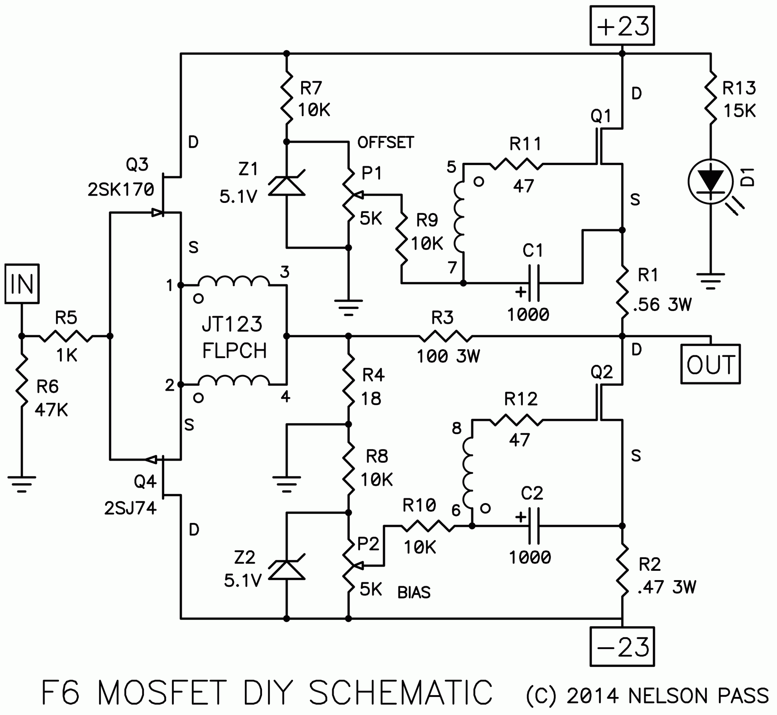
Directly below is the original circuit from F6 Article with degeneration.
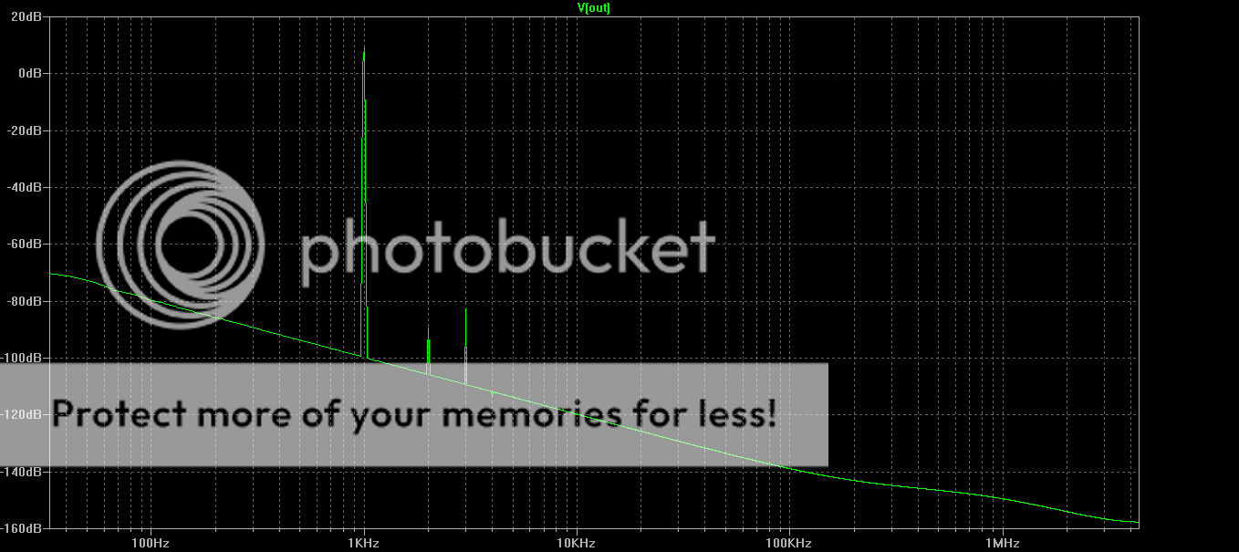
In this circuit using 0.56 Ohms and 0.47 Ohms source resistance gives the following results in simulation. Here we see a dominant second harmonic due to the mismatch in resistance of the degenerating source resistors.
All measurements are performed at 1 Watt avg into 8 Ohms (biased at 1.3A)
Increasing the differential in source resistance further to 0.56 Ohms and 0.23 Ohms increases the second harmonic significantly.
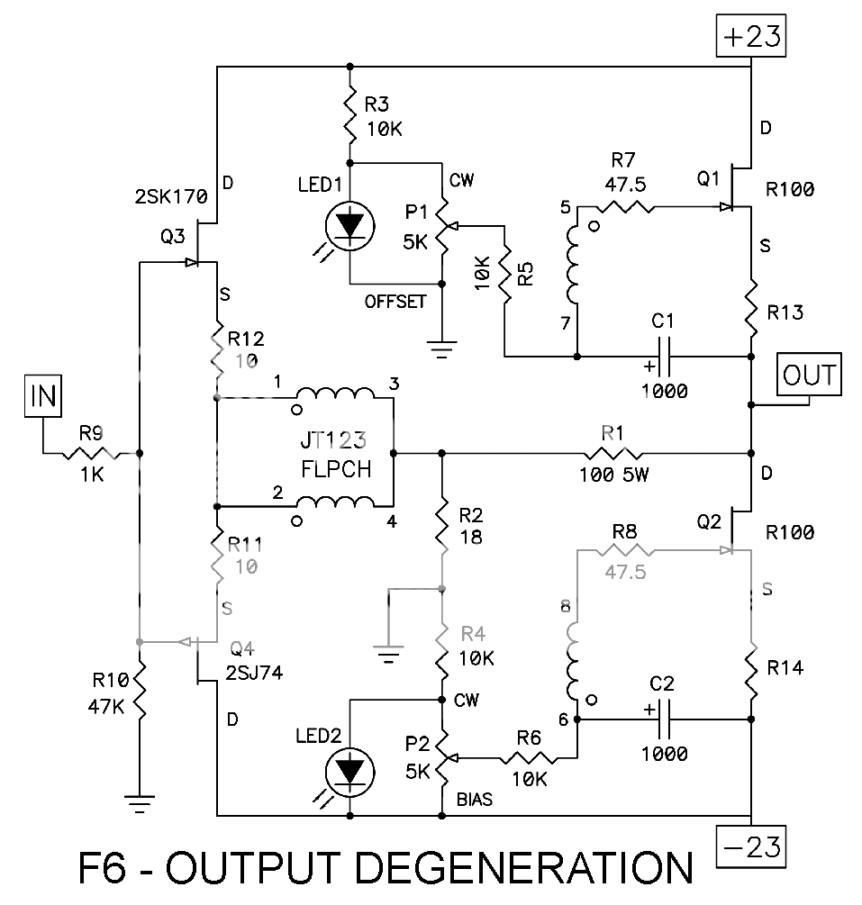
The DIYAUDIO PCB is based on the circuit below. This circuit behaves quite a bit differently.
If the difference is not obvious, looking at the source pin of the mosfet you will notice that it is connected directly to the 1000uF capacitor (C1, and C2). In the original circuit (shown above) this is not the case. The effect of this, is now the source resistor values no longer control the level of 2nd Harmonic.
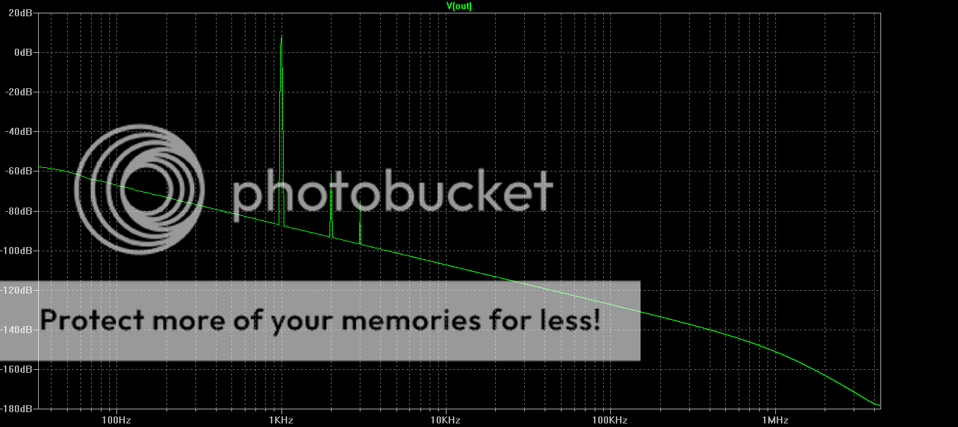
In this circuit using 0.56 Ohms and 0.47 Ohms source resistance gives the following results in simulation.
1 Watt avg into 8 Ohms (biased at 1.3A). No dominant 2nd harmonic is observed.

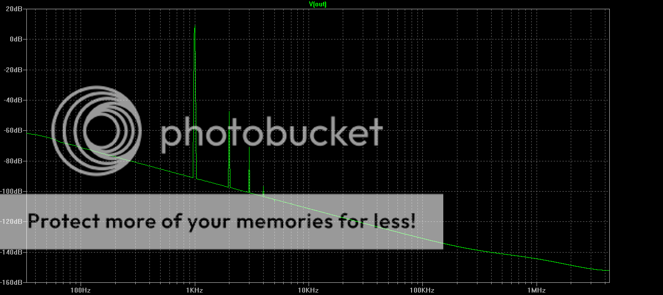
Increasing the differential in source resistance to 0.56 Ohms and 0.23 Ohms does very little. (ie still no dominant 2nd harmonic)
To confirm this result I pulled out my distortion analyzer to test the amplifier.
The video is crap, but it shows the effect of changing source resistance on the fly.
The distortion meter is setup to just measure the second harmonic.
First measurment is with 0.56 Ohms and 0.47 Ohms. Second measurement performed on the fly is with 0.56 Ohms and 0.235 Ohms (2 x 0.47 in parallel).
Both measurements read 2nd Harmonic as -76dB, ie the resistance value has no significant effect on 2nd Harmonic, which is consistent with the result in simulation. Check out the video to see for yourself.
https://www.youtube.com/watch?v=7nJWP_DUaBY
Note: If you are wondering why 2nd harmonic is -76dB it is because I intentionally chose devices with some mismatch in transconductance, to achieve this.
Chances are, most people won't have matched devices anyway, so this probably won't matter to most people, but from a technical point of view if you want to add 2nd harmonic you will need to reroute the cap leads to the other side of the resistor lead to get this.
Damping Factor
This is where it gets a little interesting.
Using 0.56 Ohms and 0.47 Ohms in both circuits above give quite different results.
The degenerating schematic from the F6 article gives a damping factor of around 5 while the circuit used for the PCB gives a damping factor of about 10.
I haven't had a chance to confirm this with lab measurements. The results were determined by simulation. Feel free to perform this measurement yourselves and let me know what you get.
If however you use a pot on one source resistor and dial in the second harmonic you desire then the damping factor is virtually unaffected ie stays around 10.
1) The schematic the DIYAUDIO Store PCB is based on does not allow 2nd harmonic adjustment through changing source resistor values.
2) The PCB circuit can be changed to the original degenerating circuit by moving cap leads to other side of resistor lead. This will restore 2nd harmonic adjustment through source resistance modification.
3) Output impedance also appears to be significantly affected (only tested in simulation).
4) As an alternative to the PCB mod, 2nd Harmonic adjustment can be altered on PCB circuit by selecting devices with different transconductance curves if one does not want to modify the PCB.
5) As an alternative to performing transconductance measurements and selecting non-matched devices for 2nd harmonic addition, installing one IRFP250 and one IRFP240 per channel will also give a dominant 2nd harmonic.
Continue reading for more. (There is a lot more to add, so keep checking back for updates)
Links to articles
https://www.firstwatt.com/f6.html
https://www.firstwatt.com/pdf/art_f6_baf.pdf
https://www.firstwatt.com/pdf/prod_f6_man.pdf
Distortion Measurements
Directly below is the original circuit from F6 Article with degeneration.
In this circuit using 0.56 Ohms and 0.47 Ohms source resistance gives the following results in simulation. Here we see a dominant second harmonic due to the mismatch in resistance of the degenerating source resistors.
All measurements are performed at 1 Watt avg into 8 Ohms (biased at 1.3A)
Increasing the differential in source resistance further to 0.56 Ohms and 0.23 Ohms increases the second harmonic significantly.
The DIYAUDIO PCB is based on the circuit below. This circuit behaves quite a bit differently.
If the difference is not obvious, looking at the source pin of the mosfet you will notice that it is connected directly to the 1000uF capacitor (C1, and C2). In the original circuit (shown above) this is not the case. The effect of this, is now the source resistor values no longer control the level of 2nd Harmonic.
In this circuit using 0.56 Ohms and 0.47 Ohms source resistance gives the following results in simulation.
1 Watt avg into 8 Ohms (biased at 1.3A). No dominant 2nd harmonic is observed.
Increasing the differential in source resistance to 0.56 Ohms and 0.23 Ohms does very little. (ie still no dominant 2nd harmonic)
To confirm this result I pulled out my distortion analyzer to test the amplifier.
The video is crap, but it shows the effect of changing source resistance on the fly.
The distortion meter is setup to just measure the second harmonic.
First measurment is with 0.56 Ohms and 0.47 Ohms. Second measurement performed on the fly is with 0.56 Ohms and 0.235 Ohms (2 x 0.47 in parallel).
Both measurements read 2nd Harmonic as -76dB, ie the resistance value has no significant effect on 2nd Harmonic, which is consistent with the result in simulation. Check out the video to see for yourself.
https://www.youtube.com/watch?v=7nJWP_DUaBY
Note: If you are wondering why 2nd harmonic is -76dB it is because I intentionally chose devices with some mismatch in transconductance, to achieve this.
Chances are, most people won't have matched devices anyway, so this probably won't matter to most people, but from a technical point of view if you want to add 2nd harmonic you will need to reroute the cap leads to the other side of the resistor lead to get this.
Damping Factor
This is where it gets a little interesting.
Using 0.56 Ohms and 0.47 Ohms in both circuits above give quite different results.
The degenerating schematic from the F6 article gives a damping factor of around 5 while the circuit used for the PCB gives a damping factor of about 10.
I haven't had a chance to confirm this with lab measurements. The results were determined by simulation. Feel free to perform this measurement yourselves and let me know what you get.
If however you use a pot on one source resistor and dial in the second harmonic you desire then the damping factor is virtually unaffected ie stays around 10.
Total Comments 0


