I have two original boards from the first GB that I dont plan to use. If anyone needs one, I can sell one or both at half price.
YHPM
")
I've run into a problem attempting to update firmware which has not occurred in the past with Windows XP.
Using Windows 7 and two different unzip programs (WinZip and 7Zip) I cannot unzip the tools. I get messages telling me that it is not a valid download, or, in other instances, that my computer does not contain a .dll program, one that appears to be part of the download package. I've wasted several hours on this today, and am making no progress.
I'm not a Windows guy, but can anyone suggest a step-by-step to get this done? My XP laptop has finally died, and I am hoping that the 7 desktop can be used to do this update.
Thanks in advance - Pat
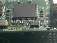
I was assembling a Chronos/Hermes/Amanero stack when I noticed what I think is a solder bridge on the first two pins of U1.
Is it supposed to be there?
Should I remove it with solder wick?
Doesn't look like it should be there. Solder wick might work, or if is soldered with lead free solder that is kind of high temp it might help to add a little 60/40 or 63/37 leaded solder and flux to make it easier to wick off.
You could try it without that first though. Good solder wick has flux in it but adding a little liquid or paste flux can help assure the solder does't oxidize while you clean up the bridge.
Also, if too much solder wicks off you can carefully add a little more. A temperature-controlled solder iron with a small tip is very much advised. Small diameter solder, maybe .4mm or a little less, and the lowest temp that melts the solder and activates the flux in the wick would also be good.
From PieterPiet
Interesting news on upcoming new firmware Amanero from CA!?
T+a dac 8 dsd - Page 73 - DAC - Digital to Analog Conversion - Computer Audiophile
@volpone and others, this is a quick update on Amanero's firmware/driver situation.
Domenico said that he will release "very soon" firmware 2004 for Linux which should take care of distortion at high DSD frequencies (mostly at 256 and 512). Furthermore, he has to readjust his new Windows driver that will work with such firmware because of a recent Windows 10 update.
How quickly and if all this is going to be implemented by T&A, I do not know. It will be up to them to validate it once it's released.
Hi sbelyo,
I just checked my Amanero board and there is no solder bridge on mine.
Personally I would remove it with a relatively thin solder wick and a quick heating and then - with a thin soldering tip and solder wire - quickly resolder the pin connections that were affected by the solder wick.
Cheers,
Jesper
I was assembling a Chronos/Hermes/Amanero stack when I noticed what I think is a solder bridge on the first two pins of U1.
Is it supposed to be there?
Should I remove it with solder wick?
I just checked my Amanero board and there is no solder bridge on mine.
Personally I would remove it with a relatively thin solder wick and a quick heating and then - with a thin soldering tip and solder wire - quickly resolder the pin connections that were affected by the solder wick.
Cheers,
Jesper
Where to the download firmware DSD512x44x48 ?There is a new firmware to support i2c , dsd512x44x48, works great with dsd512 and slave clock under Windows.
Tks u
Where to the download firmware DSD512x44x48 ?
Tks u
It is at the end of the cpu firmware list using oemtool 1.17
I stitched quite old _1096c4w2 and it is no different from dsd512x44x48.
oemtool118
oemtool118
I was assembling a Chronos/Hermes/Amanero stack when I noticed what I think is a solder bridge on the first two pins of U1.
Is it supposed to be there?
Should I remove it with solder wick?
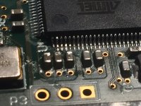
well, I made it worse by not waiting for the solder wick. I bridged anther pin or two. The solder wick cam and i was able to remove all the bridges but it looks like I lifted the pad under that first pin
Not sure if it's going to work but I'll try it
Here's the post with the before pic
USB to I2S 384Khz - DSD Converter
Attachments
In ConfigOEM110, there is a firmware listed called "L-L_R-R" - does anyone have any information about this? Does it by any chance put out inverted data enabling balanced operation of the TDA1541/PCM1704/etc chips?
Thanks in advance for any information!
No need. You can use the 74LVC2G86 to make different L-L/R-R as below on DSD DSC 2
DSC V2.0.pdf - Google Drive
well, I made it worse by not waiting for the solder wick. I bridged anther pin or two. The solder wick cam and i was able to remove all the bridges but it looks like I lifted the pad under that first pin
Not sure if it's going to work but I'll try it
Here's the post with the before pic
USB to I2S 384Khz - DSD Converter
My PC did recognize it when plugged in
- Home
- Vendor's Bazaar
- USB to I2S 384Khz - DSD Converter