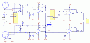
yes, can be supplied from any voltage in range of +-12V to +-60V if the voltage regulator ballast resistors are properly chosed.
Then I would like to buy 3 of them, setup to support the voltage range from my
Hello Cristi!Long awaited TA3020 KIT available: Connexelectronic

Display the schematics or project for SMPS +/-35V/2x5A.

thanks
Last edited:
Linear Power supply with auxilliary power supplies and complete protection for class D and T amplifiers: Connexelectronic
The BIPS module acctually needs +-12V for proper operation, but when is used with TA3020 amplifiers or similar, it can be powered from higher voltage, such as +-40 to +-60V, on board there are 2 resistors and 2 zenner diodes to limit the voltage to 12V. if the auxilliary output of any smps is used, which provide +-12V or close value, the resistors value can be reduced or even eliminated and supply the board from the aux. directly.
Hi I bought a BIPS and waiting the delivery. Do you have the schematics and other documentation please ? Thx
I attached the BIPS schematic on the forum in few places, i will do it again here.
what need to consider is R5, R16 which set the overall gain, in this case 1. if other value is needed, can be chosen by the ratio of R5/R3 for left channel and R16/R22+1 for right channel. the op-amps are supplied through the 1W resistors and 12V zenner diodes. the resistors should be chosen to allow BIPS to be supplied with the available voltage, which can be in range of +-12V to +-60V. for +-12V, 33-56R resistors should be used, and for +-60V 2k2-2k7/1W resistors should be used.
what need to consider is R5, R16 which set the overall gain, in this case 1. if other value is needed, can be chosen by the ratio of R5/R3 for left channel and R16/R22+1 for right channel. the op-amps are supplied through the 1W resistors and 12V zenner diodes. the resistors should be chosen to allow BIPS to be supplied with the available voltage, which can be in range of +-12V to +-60V. for +-12V, 33-56R resistors should be used, and for +-60V 2k2-2k7/1W resistors should be used.
Attachments
Pin #1 of an XLR connector should be connected directly to the chassis, it should NOT be connect to the audio circuit ground. The audio circuit ground may also be connected to the chassis, but that's another matter. The XLR pin #1 is a shield, it is not a part of the audio circuit.
TA2022SMPS Amplifier : http://connexelectronic.com/product_info.php/cPath/39_47/products_id/140
Last edited:
Andrew, the BIPS is NOT attenuating the input signal that much, you might be confused by the marking of the resistors, i use the smd codes, easier for those who assembly the boards. the values are as follows:
911 = 910R
912 = 9K1
103 = 10K
561 = 560R
Speedskater: you're right, but this board is the point where the GND must be connected to the chassis, and as in many application, the pin 1 is connected to GND. i've seen in many PA schematics that the pin is connected directly, just in some power amps there is a GND lift switch, which break the direct connection, leaving one resistor and capacitor between the pin 1 and chassis.
I attached the BIPS schematic on the forum in few places, i will do it again here.
what need to consider is R5, R16 which set the overall gain, in this case 1. if other value is needed, can be chosen by the ratio of R5/R3 for left channel and R16/R22+1 for right channel. the op-amps are supplied through the 1W resistors and 12V zenner diodes. the resistors should be chosen to allow BIPS to be supplied with the available voltage, which can be in range of +-12V to +-60V. for +-12V, 33-56R resistors should be used, and for +-60V 2k2-2k7/1W resistors should be used.
Thank you
Not arrived yet mi BIPS, but it should be the next days.
Can we change the Opamp, it is assembled with a socket?
Regards
CxD300-8R Connexelectronic
The best performance/price ratio IRS2092 amplifier module on the market.
Interesting.
Question; your site says "Output power typically 250W on 8R impedance supplied with +-72V".
I calculate only 77% efficiency from that; is that correct?
Also, you have so many IRS2092-based amps now that it's hard to choose.
For the same power, you can spend more or less, so presumably there are reasons for spending more.
What are they?
Thanks
- Status
- Not open for further replies.
- Home
- Vendor's Bazaar
- NEW Audio amplifier kits, modules and many others.
