FALL BACK FOR J...
Hi John,
Now it's my time not to understand why refer to the other thread?
SY,
With your permission:
but a chacun son gout or chacun a son gout.(the former not being the same as the latter).")
Ciao,
Hi John,
Now it's my time not to understand why refer to the other thread?
SY,
but chaque un a son gout.
With your permission:
but a chacun son gout or chacun a son gout.(the former not being the same as the latter).
Ciao,
dhaen:
Well, yeah, if you want an amp to have a "sound," I can see the point. 2ndHD is appealling to many listeners. But Joel has said that his goal is an amp that is sonically transparent. So, I'm still somewhat mystified as to why, with this design goal, one would start with a topology which is prone to large amounts of distortion, even order or otherwise. PP will have a considerably lower amount of THD and IM (I find the argument that an amp with 3% 2ndHD and 1% 3rdHD should be thought of as "better" than an amp with 0.05% THD completely baffling). Much of the complication of these circuits is meant to circumvent the high distortion one would get otherwise- the expression "polishing a turd" comes to mind.
But admittedly, a lot of things in audiophilia mystify me. Why do I use tubes anyway?
Frank, the reference to the thread was that having produced a balanced system that cancelled even harmonics, it "souded" better when it was unbalanced.
Sy, I'm hardly here to defend Joel. He'll want to do that himself.
I do have a opinion that the "harmonic signature" has to be taken as a whole. Chopping out every other energy peak with that "comb filter" called push-pull, can give some undesirable effects.
In the mean time, I'll listen to my SET.
Cheers,
OTL SE.
Hi,
Well yes...
But knowing Joel wanted to build a SE OTL I pointed to the Philips SRPP circuit or IMO even better the White CF, a circuit that would really shine in this application.
As you see for yourself he chose otherwise.
I remedied my frustration with a session and some aspirine.
Let's wait and see it may please him after all...
Cheers,
Hi,
PP will have a considerably lower amount of THD and IM (I find the argument that an amp with 3% 2ndHD and 1% 3rdHD should be thought of as "better" than an amp with 0.05% THD completely baffling). Much of the complication of these circuits is meant to circumvent the high distortion one would get otherwise- the expression "polishing a turd" comes to mind.
Well yes...
But knowing Joel wanted to build a SE OTL I pointed to the Philips SRPP circuit or IMO even better the White CF, a circuit that would really shine in this application.
As you see for yourself he chose otherwise.
I remedied my frustration with a
session and some aspirine.Let's wait and see it may please him after all...
Cheers,
SY said:But admittedly, a lot of things in audiophilia mystify me. Why do I use tubes anyway?
I rest my case.
also...
To Frank, and whom it may concern - it's very easy to sit back with an air of superiority and look down on other people's design "errors", while offering none of your own.
I have yet to see a de grove circuit. I suspect there isn't one.
In fact, none of the most critical members have posted a design of their own - that I've seen. Alert me if I'm wrong.
Genuine suggestions are welcome. Idiotic jokes and condescension are not.


dhaen said:The resistor was in series with the energy being recovered from the choke; low efficiency.
Ok John, phew! I thought for a minute there that there was some crazy law of induction I wasn't aware of!


Joel: Once I figure out how to get schematics drawn on my computer and get them into an uploadable format, I'll post some designs that I'm currently using. You'll note a pretty thorough description of my preamp design in the servo thread. I welcome your criticism.
I'm pretty good with circuits- I'm pretty bad with computers. A man has got to know his limitations.
I'm pretty good with circuits- I'm pretty bad with computers. A man has got to know his limitations.
That would be too easy- my schematics are drawn in my lab notebook. No scanner, alas. I have AutoCad capability, but no library of symbols for it. Frank sent me some bmp symbols, but figuring out how to use them properly will have to wait until I'm finished my next travel jag (starting this weekend, back at the end of this month). But my New Year's resolution was to get digital with schematics, so...
OTL continued...
Hi,
How much power into 8 Ohm would you require?
Also,I notice you don't have an e-mail address for the forum.
Cheers,
Hi,
could someone please post here or send me the schematic (with components values) of a good OTL design (such as GRAAF GM-20 or Atma-sphere stuff)?
How much power into 8 Ohm would you require?
Also,I notice you don't have an e-mail address for the forum.
Cheers,
Ooopss...
marcello.pellerano@libero.it !!
Thanks Frank,
I think that a 20W beast will be fine for my purposes, so the Graaf GM20 schematic will be perfect.
Cheers
Marcello
marcello.pellerano@libero.it !!
Thanks Frank,
I think that a 20W beast will be fine for my purposes, so the Graaf GM20 schematic will be perfect.
Cheers
Marcello
I was right... sort of.
John - although I drew it wrong, you actually can have a gas tube as a load for the cathode follower. This is right out of the RDH.
The first tube "has no dc load on it", and "nearly all of the signal voltage is dropped across the resistor" (2500 ohm).
The resistor could of course be replaced by a choke.
Attachments
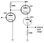
I don't have mine to hand, but: All the gas tube is doing in this case is providing a DC offset. In no way is it a "load" to my way of thinking.This is right out of the RDH
Are you after an amplifier or an "effects generator"?The resistor could of course be replaced by a choke.
Putting a choke in series with a gas tube will create some strange and wonderful effects.

You must consider that the "strike" and "maintain" voltages are different.
Lesson over....
- Status
- This old topic is closed. If you want to reopen this topic, contact a moderator using the "Report Post" button.
- Home
- Amplifiers
- Tubes / Valves
- OTL, continued...