Electrolytic caps...
No flames, but:
Cheers,
PS I don't like 'lytics either..")
No flames, but:
But the power supply is in the signal path...(electrolytic caps)...have no place in the signal path and belong in the power supply
Cheers,
PS I don't like 'lytics either..
Re: I think you know what I mean
Then I suggest you never do that.
316a said:...there is a place for electrolytics and in series between amp and speaker is not one of them .
Then I suggest you never do that.
Richard,
That would work fine.
As would, arranging for the cathode to be at zero volts, through some power supply trickery. But then one might consider the power supply caps to be in series with the speaker / load.
But aren't they always..
Just my little bit of mischief - in Franks absence someone must
Cheers,
Absolutely.How about having 2 sides and taking the output across the cathodes?
That would work fine.As would, arranging for the cathode to be at zero volts, through some power supply trickery.
But then one might consider the power supply caps to be in series with the speaker / load. But aren't they always..
Just my little bit of mischief - in Franks absence someone must
Cheers,
Re: Re: I think you know what I mean
...of course I won't . It would sound *******ing awful ! Happy ears !
316a
Joel said:
Then I suggest you never do that.
...of course I won't . It would sound *******ing awful ! Happy ears !
316a
CAPS
Hi,
The PSU caps of all anode loaded stages are in series with the output stages,which is not the same as having the output cap in series with the signal path however.
That doesn't mean the PSU caps' quality does not reflect on the signal outputs' quality either.
In fact I always say one listens to a PSU,not an amplifier.
I'm back,
Hi,
As would, arranging for the cathode to be at zero volts, through some power supply trickery. But then one might consider the power supply caps to be in series with the speaker / load
The PSU caps of all anode loaded stages are in series with the output stages,which is not the same as having the output cap in series with the signal path however.
That doesn't mean the PSU caps' quality does not reflect on the signal outputs' quality either.
In fact I always say one listens to a PSU,not an amplifier.
I'm back,
Sematics
Frank,
I said:
The only difference between Joel's output cap, and a PS smoothing cap, is the latter has some extra stuff hanging off it, which will hardly help.
Cheers,
Frank,
I don't believe that's what I said.The PSU caps of all anode loaded stages are in series with the output stages,which is not the same as having the output cap in series with the signal path however.
I said:
Which I believe to be the case.But then one might consider the power supply caps to be in series with the speaker / load.
The only difference between Joel's output cap, and a PS smoothing cap, is the latter has some extra stuff hanging off it, which will hardly help.
Cheers,
YEP.
Hi,
Given an OTL output stage, one may say the PSU caps are in series with the speaker load (to me they are, no matter how you turn them).
As they are on so many other occasions anyway.
Saying that this has the same deleterious effect as running the signal straight through an electrolytic cap is a bit of an overstatement IMO.
Which brings me to square one:all psu components are in the signal path.
The tricks to minimize the effects I'll try to explain in the PSU thread.
Cheers,
Hi,
The only difference between Joel's output cap, and a PS smoothing cap, is the latter has some extra stuff hanging off it, which will hardly help.
Given an OTL output stage, one may say the PSU caps are in series with the speaker load (to me they are, no matter how you turn them).
As they are on so many other occasions anyway.
Saying that this has the same deleterious effect as running the signal straight through an electrolytic cap is a bit of an overstatement IMO.
Which brings me to square one:all psu components are in the signal path.
The tricks to minimize the effects I'll try to explain in the PSU thread.
Cheers,
The tricks to minimize the effects I'll try to explain in the PSU thread.
Were all ears Frank,

IN A HURRY?
Hi,
Neither do I.
Let's wait till my "Kasteelbier' kicks in then?
Hi,
I haven't got all night
Neither do I.
Let's wait till my "Kasteelbier' kicks in then?
Hello,
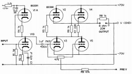
Well, this one uses the same output tubes .
Also, does anyone tried this version, any comment on sound ?
Best regards,
Kristijan Kljucaric
http://web.vip.hr/pcb-design.vip
could someone please post here or send me the schematic (with components values) of a good OTL design (such as GRAAF GM-20 or Atma-sphere stuff)?
Well, this one uses the same output tubes
.Also, does anyone tried this version, any comment on sound ?
Best regards,
Kristijan Kljucaric
http://web.vip.hr/pcb-design.vip
Attachments
AT LONG LAST...
Hi,
Pardon my sarcasm on the first bias supplies.
Honestly they showed a lack of understanding beyond (my) belief.
What you present is a bias supplly allowing you to corrrect some inballance at least.
This is exactly what _arg and myself have been discussing off "forum" for a while.
The Cufioli circuit may seems complex,in reality it is made complex for no reason at all.
With all OTL circuits,pay attention to the PSU.
Cheers,
Hi,
EC360 I dont think is a very common tube and can be difficult to source.
Where did you get the schematic? It is not possible to get 20W from only 4 of these tubes especially with only +- 70V anode voltage. The EC 360 is only specified to max 250mA current which doesn't take you very far, you need ~2.5A peak to get 20W. The 6C33C can give you this current but then you need a voltage of ~140V minimum.
Regards Hans
Hi Hans!
Thanks for the answers!
Here in Hungary some people built it already and it works. I try to get contact with them for more info. I think the schematic comes from an amp "cookbook", but I would like ask here some international tube guru for oppinions. I read the EC360 can easily work on such a low voltage and with 200mA. May be the 20W output is a dream, but the main question is: could this circuit work or is there any error?
Thanks!
Hi,
It should work as far as I can tell.
BTW, the EC360 was only made by one factory in the ex-DDR if my information is correct.
Cheers,
but the main question is: could this circuit work or is there any error?
It should work as far as I can tell.
BTW, the EC360 was only made by one factory in the ex-DDR if my information is correct.
Cheers,
- Status
- This old topic is closed. If you want to reopen this topic, contact a moderator using the "Report Post" button.
- Home
- Amplifiers
- Tubes / Valves
- OTL, continued...