May be the 20W output is a dream, but the main question is: could this circuit work or is there any error?
Yes, I think it can work, I built something similar as my first experiment with OTL long time ago. It is actually a SRPP or as Walley and Wallman described a "Two tube series arrangement"
The output power will be ~1W max
The balancing of the gridvoltage to the lower tubes looks like something a designer with only experience of transistors has put together, it doesn't work as there is no grid current and therefore the gridvoltages stay the same what ever setting of the 47kohm pot. A better way of balancing is to vary the upper cathode resistors or to use cathode bias for the lower tubes using a pot.
The output impedance of this circuit is quite high ~60 ohm which doesn't help for keeping a flat frequency response of the connected speaker.
Philips built many similar amplifiers with EL86 tubes and 800ohms speakers and they worked well but with high distorsion and low output power.
I am doubting that anyone have really built this amplifier as it is described, the exagurated output power and the nonfunctioning balance scheme together with the unpractically high output impedance makes me doubtful.
Regards Hans
Hi,
If I remember the type number correctly, I once owned a Philips 9016 using a pair of EL86s. You could configure it by removing a little plate for either 1:1 xformer output or capcoupled.
Power was rated at ~8 Watt into 800 Ohm. Much to my surprise it worked rather well with my 8 Ohm 92dB/1M speakers.
It used cathode bias as Hans suggests...
I just wonder why they never used a WCF as output, IMO this should work much better with modern speakers.
Cheers,")
Philips built many similar amplifiers with EL86 tubes and 800ohms speakers and they worked well but with high distorsion and low output power.
If I remember the type number correctly, I once owned a Philips 9016 using a pair of EL86s. You could configure it by removing a little plate for either 1:1 xformer output or capcoupled.
Power was rated at ~8 Watt into 800 Ohm. Much to my surprise it worked rather well with my 8 Ohm 92dB/1M speakers.
It used cathode bias as Hans suggests...
I just wonder why they never used a WCF as output, IMO this should work much better with modern speakers.
Cheers,
OTL with EC360
Frank and Hans!
Thanks a lot for your answers! Arigato gosai mas!
I am sad now, becouse I was afraid of what you told me. I don't understand why people write a book with such a lie and with so much defective infos...
I still try to get contact with builders to get theirs results.
Could you tell me how to build a low voltage, simple OTL or to rectify this schematic? ( may be with 6 EC360, etc. ) For me 8-10W would be enough.
BTW, the EC360 was used in medical machines and there are stil a lot in store-rooms.
Thanks again!
Tyimo
Hi,
Well if it's any consolation, I've seen that circuit with the EC 360 before too.
It can be made to work but to my mind it's just not worth the trouble.
If you don't mind going push-pull it won't be too hard to make a nice OTL amp with four to six valves per channel.
From the little data I have, one could consider the EC 360 as a 6AS7G with both sections in //....sort of.
All it requires is a bipolar rail of about 150V some 20mA through the valve using fixed bias, a phase splitter/driver and a voltage amp.
Again I'm simplifying just to give you an idea.
Please have a look at the various OTL schematics that were posted already and tell us what you'd like to do.
Cheers,
I am sad now, becouse I was afraid of what you told me. I don't understand why people write a book with such a lie and with so much defective infos...
Well if it's any consolation, I've seen that circuit with the EC 360 before too.
It can be made to work but to my mind it's just not worth the trouble.
If you don't mind going push-pull it won't be too hard to make a nice OTL amp with four to six valves per channel.
From the little data I have, one could consider the EC 360 as a 6AS7G with both sections in //....sort of.
All it requires is a bipolar rail of about 150V some 20mA through the valve using fixed bias, a phase splitter/driver and a voltage amp.
Again I'm simplifying just to give you an idea.
Please have a look at the various OTL schematics that were posted already and tell us what you'd like to do.
Cheers,
For me 8-10W would be enough.
I think you could get that or slightly more into 8 ohms with 2 6AS7G's running off of +/- 150VDC. You could probably do a bit better than that with 2 6C33Cs. Of course, you'd need feedback with this few output tubes to develop some damping factor.
Hi,
Not sure but I think we have to stick with the EC360...Let's see.
Cheers,
I think you could get that or slightly more into 8 ohms with 2 6AS7G's running off of +/- 150VDC.
Not sure but I think we have to stick with the EC360...Let's see.
Cheers,
Say, anybody have a full datasheet on the ec360? 
It just might have more OTL potential than that goofy little schematic indicates. I really wouldn't design with a tube I couldn't get a reasonably complete set of data on, anyway, including a full set of design center and/or max. ratings and preferably plate curves.
It just might have more OTL potential than that goofy little schematic indicates. I really wouldn't design with a tube I couldn't get a reasonably complete set of data on, anyway, including a full set of design center and/or max. ratings and preferably plate curves.
I think you could get that or slightly more into 8 ohms with 2 6AS7G's running off of +/- 150VDC. You could probably do a bit better than that with 2 6C33Cs.
2 6C33C's can easily give 25W or even more in 8 ohm with a measured ouput impedance of 10.5 ohm using an inverted Futterman setup.
However 4 EC360's can probably give something similar, (I dont know how these can take the abuse in an OTL but heater power seem to be high enough for providing reasonable anode current)
You can see my OTL schematic here http://www2.gol.com/users/tube/otl.html I think it would work quite well replacing the 2 6C33C's with 4 EC360's, it can probably give almost the same ouput power, you can mail me for more details.
Regards Hans
ALL YOU WANT BUT CURVES...
Hi,
Same here...it's an interesting little ****** though:
EC 360
EC 360 RFT DATA
As you'll no doubt notice this is a high perveance tube making it suited for excellent service as a series pass device.
Cheers,
Hi,
I really wouldn't design with a tube I couldn't get a reasonably complete set of data on, anyway, including a full set of design center and/or max. ratings and preferably plate curves.
Same here...it's an interesting little ****** though:
EC 360
EC 360 RFT DATA
As you'll no doubt notice this is a high perveance tube making it suited for excellent service as a series pass device.
Cheers,
Frank, Hans, Thoriated!
Thanks a lot! What about to use 6C41C?
Frank could you give me (or us) a schematic about your idea?
One think would be still good: the amp could working under 100V if it is possible!
Thanks and greets!
Tyimo
Thanks a lot! What about to use 6C41C?
All it requires is a bipolar rail of about 150V some 20mA through the valve using fixed bias, a phase splitter/driver and a voltage amp
Frank could you give me (or us) a schematic about your idea?
One think would be still good: the amp could working under 100V if it is possible!
Thanks and greets!
Tyimo
Hi,
The 6C41-C is about half a 6C33-C so should a good candidate.
I haven't seen much people building with this valve though.
Regarding the idea, well it certainly isn't mine...I was just thinking about the "classic" PP amps a la Futterman, Technics, Taki, Takesue, Wiggins etc.
If you feel like reading up on the matter:
OTL.
There is plenty of experience present here on the forum so I suppose everyone will chip in.
Cheers,
P.S. Why stick to 100V ?
Hi!
O.K. I was wrong: I mean 6C47C, with brutal 2500mA on 70V!
Why stick to 100V? Because I have some very big Philips Caps and a nice Hipersil transformator already!
I would like a simple SE OTL, if possible under 100V and with 8-10W.
I read the OTL thread, but I didn't get closer to my plans...This is why I thought on the schem with the EC360.
Thanks again!
Greets
Hi,
Somehow I got the feeling you mean the Russian EL509, 6KG6, 6P45S?
Cheers,
O.K. I was wrong: I mean 6C47C, with brutal 2500mA on 70V!
Somehow I got the feeling you mean the Russian EL509, 6KG6, 6P45S?
Cheers,

Hi,
If it is what I think it is....It's only a pulse current measurement done on a EL/PL519.
Cheers,
2.5A @ 70V thats some valve
If it is what I think it is....It's only a pulse current measurement done on a EL/PL519.
Cheers,
Hi,
One is based on the other:
Cheers,
Well if it's any consolation, I've seen that circuit with the EC 360 before too.
One is based on the other:
Cheers,
Attachments
2.5A @ 70V thats some valve
Beware of pulse measurements like this, as I wrote before oxide coated cathodes can support much higher currents during pulse conditions then for steady state, for an OTL this is not valid as the tubes need to support high current during longer period with low frequency tones.
It is possible to get some idea of the current a tube can support by checking the heater power, the higher the heater power the higher continous cathode current can be supported.
As an example the 6C33C draw 6.5A at 6.3V or ~41W, this tube is rated to support 550mA continous current but works well in OTL where it easily can give 2.5A without ill effects. The EL509 or PL519 have only ~12W heater power and although it is specified at 500mA continous current you can not assume that it is able to support the same current as a 6C33C. I dont know the 6C47 but would be interested i this one IF: it is a triode, it has reasonable heater power, and is generally available.
Heater power is one thing but in order to support high current at low voltage you also need a tube with low Ri and high Gm, the tubes if they are triodes have extremely small distance between cathode and grid and are therefore more sensitive to mechanical manufactoring tolerances then more normal tubes. The tubes with lowest anode voltage for a given current are penthodes, an example is PL519 that can give 1.5A, (at least during pulse conditions) with anode voltage 70V, BUT that is with a screen grid voltage of 190V and significant screen current that make the tube very unlinear during these conditions. My conclusion is that it is better and safer to use a triode like 6C33 with somewhat higher anode voltage but with better linearity and also with more assurance that it will be possible to source tubes in the future that have the same performance.
Regards Hans
Hi!
Frank! I mean the 6c47C power triode. May be I am wrong, but I heard it is brutal. What I only find is the attached data pic. where the IA is 2500mA on 70V.
Thanks for the Cameroni schem! Is it work?!) What could be lowest voltage for it? Do you know the parts values too?
I continue the investigation for the EC360 builders...
Thanks and greets!
Tyimo
Frank! I mean the 6c47C power triode. May be I am wrong, but I heard it is brutal. What I only find is the attached data pic. where the IA is 2500mA on 70V.
Thanks for the Cameroni schem! Is it work?!
) What could be lowest voltage for it? Do you know the parts values too?I continue the investigation for the EC360 builders...
Thanks and greets!
Tyimo
Attachments
Hi,
It should but I don't think there's enough there to get it going.
Here's where I first saw it:
CAMORANI OTL
Unfortunately I don't have a copy of the Sound Practices issue.
Still, expect B+ to be well above 100 VDC.
From what I understand mr Camorani is an engineer who also runs an audio company called AudioNautes.
Regarding that super 6C47C...Is this for real???
My goodness, this seems yet another of those military secret tubes no one has ever seen.
Can one actually buys these in Hungary?
Cheers,
Thanks for the Cameroni schem! Is it work?!
It should but I don't think there's enough there to get it going.
Here's where I first saw it:
CAMORANI OTL
Unfortunately I don't have a copy of the Sound Practices issue.
Still, expect B+ to be well above 100 VDC.
From what I understand mr Camorani is an engineer who also runs an audio company called AudioNautes.
Regarding that super 6C47C...Is this for real???
My goodness, this seems yet another of those military secret tubes no one has ever seen.
Can one actually buys these in Hungary?
Cheers,
Hi,
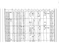
The table with data of Russian tubes looks a bit strange to me, column 3 is clearly heater voltage but if column 4 is heater current there are some errors, for instance for 6C33C.
Tyimo, can you tell us what each column means in the table? then it is much easier to judge if this 6C47 is for real or not.
Regards Hans
- Status
- This old topic is closed. If you want to reopen this topic, contact a moderator using the "Report Post" button.
- Home
- Amplifiers
- Tubes / Valves
- OTL, continued...