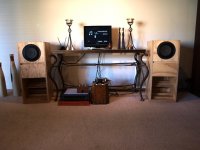
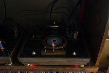
Here is a shot of my 1920s tube based (UX-171-A) Intermezzo amp with Fostex FE206En backloaded horns, Oppo BDP-95, 4SUniversal single stage 12AU7 tube amp with BoZ buffer stage and all wire-wrap inter-connects and speaker wire. The rec. tube is a 1940s 80.
Very transparent.
Very transparent.
Attachments
Last edited:
Here is a shot of my 1920s tube based (UX-171-A) Intermezzo amp with Fostex FE206En backloaded horns
Very cool!
Nice work!I love the vintage look.I always strive for this in my projects as well.Taking inspiration from the lovley old table radios of generations past,and throwing in a little steampunk as well.Here is a shot of my 1920s tube based (UX-171-A) Intermezzo amp with Fostex FE206En backloaded horns, Oppo BDP-95, 4SUniversal single stage 12AU7 tube amp with BoZ buffer stage and all wire-wrap inter-connects and speaker wire. The rec. tube is a 1940s 80.
Very transparent.
What's the story with those Fostex FE206En's?They look nothing like mine!
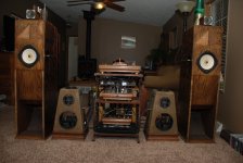
The speakers are Fostex FE206En in the backloaded horn boxes.Nice work!I love the vintage look.I always strive for this in my projects as well.Taking inspiration from the lovley old table radios of generations past,and throwing in a little steampunk as well.
What's the story with those Fostex FE206En's?They look nothing like mine!
More about the hybrid splitter
At the risk of drifting off-topic for this thread, here are a few more details about the hybrid splitter:
After considering many splitter topologies, I finally settled on using a Long Tailed Pair, since
a) it is able to swing to the full supply rail unlike the split-load "accordian" splitter"
b) Both outputs are equal and opposite, unlike the floating paraphase types in which one output has almost no second-order THD and the other output does - and the outputs also have different clipping behavior
The LTP avoids both these issues, but performs acceptably only when operating into a constant current sink. This is often approximated with a large cathode resistor, but that's usually a long way from an active constant current source. Of course a tetrode or pentode could also be used for this at the expense of great complication. A constant voltage at the base of a bipolar device translates into a constant current at its collector, given a high beta. Seems like just the thing...
Rather than derive the base voltage of the bipolar current sink from a fixed (regulated) voltage source, it's derived from the combined plate voltages of both halves of the 12AX7.
DC analysis:
The two 820k resistors are equivalent to a single 410k resistance fed ftom the plate voltage of either section of the 12AX7. the value 820k is chosen to be much higher than the 82k plate loads of the 12AX7 so they should have minimal effect on plate loading.
I'd like about 1mA Ib for each section, running the plates at about 200V (as we'll see). The two 820k resistors combine to 410k, and in series with the 2200 ohm resistor form a divider to produce about 1.2V at the base of the NPN device. Subtracting 0.6V for Vbe we have 0.6 V across the 330 ohm Re. Thus the emitter current is 1.8 mA. For devices with high beta, the collector current is about this same value, so each half of the 12AX7 has a cathode current of 0.9 mA. Since Ip=Ik, the 82k plate load has 0.9 mA through it, dropping 75V from 300, leaving the plate voltage at 225. (It's not exactly 200 V due to the fact that I'm using 0.6 V as the value for Vbe in this example -the actual value is slightly higher).
The fun starts when we look at the AC signal:
If the two halves of the pair are perfectly balanced, one plate will be swinging more positive while the other is swinging more negative, and the combined AC voltage at the junction of the two 820k will be zero, leaving only the 200 VDC component.
Let's say the two halves don't have identical mu, and the input side has a higher gain than the feedback side of the pair. In this case, the voltage at the junction of the 820k will be an AC signal, out of phase with the input signal. This causes an AC variation on the base voltage which in turn modulates the collector current in such a way as to place an AC signal on the cathodes in-phase with the input signal, of exactly the right amplitude to cancel out the excessive gain of the input side of the pair.
It can be seen that the AC balance of the differential pair is now primarily dependent on the match of the two 820k resistors, and is now much less dependent on the intrinsic mu of each triode section. Using standard 1% resistors with no special matching, I measured a 65 dB Common Mode Rejection Ratio (both halves of the splitter driven from the same source). Very good balance indeed!
So now we have a self-balancing circuit without the need to hand-select 12AX7s, also a very high impedance current sink in the cathode circuit, and also a form of local feedback within this stage to improve balance.
Since the 6SN7 driver also operates as a differential amplifier, we may as well employ this same technique there as well, to preserve good balanace going into the KT88s.
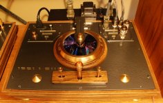
CD player
Jumpin' Jehoshaphat, that is the coolest thing ever!!!!

Seriously, it's wonderful!
PLEASE, more photos!
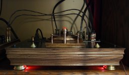
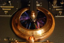
CD player
Your CD player is... pure evil...
"The Eye [of Sauron] was rimmed with fire, but was itself glazed, yellow as a cat's, watchful and intent, and the black slit of its pupil opened on a pit, a window into nothing."
I want one.
Thanks for all the great comments.That Cd player was a rather ambitious project to say the least.I enjoyed challenging my engineering and fabricating skills and gettting to use the 110 year old metal lathe I inherited from my dad.He would be proud to see this.I think my next project might be a little more "normal"...naaa.I am kidding,I can't do normal.
Thanks for all the great comments.That Cd player was a rather ambitious project to say the least.I enjoyed challenging my engineering and fabricating skills and gettting to use the 110 year old metal lathe I inherited from my dad.He would be proud to see this.I think my next project might be a little more "normal"...naaa.I am kidding,I can't do normal.
He would be I'm sure.
- Home
- Amplifiers
- Tubes / Valves
- Photo Gallery