The little disadvantage is a few dB bump at about 10Hz, due to the gyrator output impedance, the parafeed capacitor value and the OPT inductance.
This will be attenuate with load resistors on BOTH sides of OPT.
Resistors value are between 8-20k, depending of capacitor capacitance and OPT inductance values.
The amplification factor will be decrease (about 1-3 dB) and LF will start downing at about 15-30Hz.
If you use cathode resistor (instead of filament bias) and don't use AC blocking capacitor, the LF roll-down slip upper (50-100Hz). IMHO 100-470uF is necessary.
Hi euro 21,
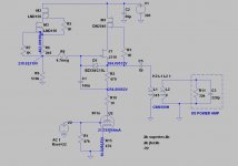
bypass capacitor is missing since this help to reduce the bump you pointed out. With 2uf cap as pictured the peak is around 0.7dB in the 10Hz area but it becomes almost flat if parafeed cap increase to 3uF. In case of bypass cap, one needs to add the damping resistance on the parafeed transformer but this will increase the output impedance too and this is not my goal (low gain+ low Zout). All this kind of evaluation has been done with the AC analysis of LTspice.
According to this seems no big issues if trying this parafeed design especially with respect to gyrator board operating points. Or am I wrong?
Anyway thanks for your comment.
Hi Ale,
according to my simulation the parafeed shows a Zout in the range of hundreds ohm (around 200 ohm) while gyrator mu-out is more than 10 times greater (so in the thousands range). This, in addition to the low gain aimed (6dB is enough) sounded more suited to my needs as soon as it was possible to keep the resonance under control. There is nothing I can add to this analysis due the fact that this implementation, for the moment, is on paper only.
according to my simulation the parafeed shows a Zout in the range of hundreds ohm (around 200 ohm) while gyrator mu-out is more than 10 times greater (so in the thousands range). This, in addition to the low gain aimed (6dB is enough) sounded more suited to my needs as soon as it was possible to keep the resonance under control. There is nothing I can add to this analysis due the fact that this implementation, for the moment, is on paper only.
Hi,
Zout should be 1/gm. The transconductance of the J310 at low VDS will be appalling. When I simulated a similar circuit with 4P1L and BF862 as the jFET, the Zout is close to 95R. I'd expect Zout to be at least below 160R with a J310 as transconductance is 12mS typically and with such low VDS may drop to half at least.
If I were to have the time, I'd traced the J310 on my tester to plot the real transconductance at low VDS.
Running a simulation for a 4P1L with a 30K, distortion is 0.02%.
In my view, forget the parafeed. 30K is a decent load to drive for a mu-follower!
cheers
Ale
Ale, I measured -live measurement in my 801 preamp- 1k2 at 1kHz (J310 - 01N100D gyrator with 220nF output capacitor).I'd expect Zout to be at least below 160R with a J310 as transconductance is 12mS typically and with such low VDS may drop to half at least.
DN2540 has 140mS G(FS) at 25mA!
I hope at Saturday evening I can replace one gyrator to the same one (containing DN2540).
I will measure output impedance on both (containing J310 and DN2540) channel.
Bela,
The DN2540 capacitances creep up with VDS<10V:

At 25mA, the GM should be around 200mS, I measured this myself. But this is at VDS=10V, at 1V you can't expect same performance:

However, the rds of the DN2540 falls down into pieces unless you're running it with VDS>1-1.5V:

Otherwise the performance is not great. Alternatively you can try Walter Jung's "impedance multiplier":


I much rather stick to the BF862 (if 25mA) or J310 if Id>25mA.
Your 220nF cap will contribute in both cases around 720 ohms of the impedance at 1kHz.
The DN2540 capacitances creep up with VDS<10V:
At 25mA, the GM should be around 200mS, I measured this myself. But this is at VDS=10V, at 1V you can't expect same performance:
However, the rds of the DN2540 falls down into pieces unless you're running it with VDS>1-1.5V:
Otherwise the performance is not great. Alternatively you can try Walter Jung's "impedance multiplier":
I much rather stick to the BF862 (if 25mA) or J310 if Id>25mA.
Your 220nF cap will contribute in both cases around 720 ohms of the impedance at 1kHz.
Last edited:
Hi Radu,
Do you like it?
01-26 switchable preamp.jpg
I'm afraid it's a bit more than "little mod".
I use my 10/801 preamp with 320-340V B+ (between 260-270V and 25-30mA operating points) and 8R bias resistor.
It's another animal than "low voltage/low current" preamps as 01a or 26.
Hi euro21,
In your schematic, 26 plate voltage is 162v. May I know how many plate voltage if using 01A ? Should I need to reduce voltage for 01a specially.
Or setup around 130v for both 26 and 01a?
")
Plate voltage is sets automatically, depends of constant current from CCS and -filament- bias.
Due to the previous parameters and 01a condition, it's vary from 115-135V.
Thank you euro21
I would try to modify according to your schematic for switchable 01a/26.
Currently, I'm using line out transformer for output.
using IRF840 for voltage regulator since SSHV in transiting to me by latest group buy.
Later, I would build the Ale's Gyrator board and compare which sound fit to me.
View attachment 887541
View attachment 887543
Last edited:
Otherwise the performance is not great. Alternatively you can try Walter Jung's "impedance multiplier":
I tried this Jung version cascade, with DN2540, and to be honest, it was the only configuration which has lead to the death of a MOSFET under switch on transient conditions.
I used a 100V capacitor, first that went with a spike, then when I replaced with a 1000V part, the MOSFET died instead.
Using a 'normal' cascade with DN2540 I had no such issue, but I was only sourcing 8mA to 12mA.
Nevertheless, I have some J112/113 and LND150 to try for this current range.
I dont think it has been mentioned before, but with some experts here I would like to pose my suspicions for a cause of CCS device failure, that I dont believe I have seen mentioned before.
As Euro21 says, the plate voltage settles as current stabilises. In my little dht, I used LED cathode bias to set the grid volts, and CCS anode load as above to set current.
Due to awful temp coeff. This settling takes some time. Any variation in filament current exacerbates the issue.
At switch on of main power, any transient current in the HT PSU, that ends up induced into the filament supply, causes massive issues, with the transient induced into the plate circuit, and then the CCS.
This is especially problematic with low filament volt/currents (1.2V in my case)
That's my pet theory.
Last edited:
- Status
- This old topic is closed. If you want to reopen this topic, contact a moderator using the "Report Post" button.
- Home
- Amplifiers
- Tubes / Valves
- DHT line stage 26, 01a or 101d