Thanks euro for posting the schematic.
I look forward to it...
I will start soon separated topic as "10/801 preamplifier", where updated schematics -preamp, HT, LT supply etc. and pictures about the constructions) will be shown.
I look forward to it...
Ale and I have set up various listening tests to compare 4P1L, 26 and 01A line stages. we've both built several examples of all three.
Ale is quite right - if you want to build a damn near perfect line stage, it's his 01A Gen 2 design. He has some PCBs and I wouldn't hesitate to contact him and start the build. It's the current state of the art.
http://www.bartola.co.uk/valves/dht-pre-amplifier/01a-preamp-gen2/
Andy, Ale,
Is the PCB for gyrator or 01a preamp?
TIA
Is the PCB for gyrator or 01a preamp?
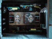
As you can see (this is my 801 preamp in building state, but other DHT preamp is similar) there are in the upper left to right Ale's gyrator -with yellow capacitor-, then Rod Coleman regulator and 50W bias resistor. Both of them are installed on heat sink.
Tube sockets (required resistors and output capacitor too) are in the suspended (3mm alu) subschassis.
Attachments
Where can I find a parts list and set-up instructions for the Ale‘s gyrator? I am not able to find anything over at his website. I am planning on buying some PCB, but holding back since I do not know if some hard to get parts are involved. Suppose he does not sell complete kits.
As you can see (this is my 801 preamp in building state, but other DHT preamp is similar) there are in the upper left to right Ale's gyrator -with yellow capacitor-, then Rod Coleman regulator and 50W bias resistor. Both of them are installed on heat sink.
Tube sockets (required resistors and output capacitor too) are in the suspended (3mm alu) subschassis.
Plenty of heatsinking! You might need it for the 801. That's a useful chassis - solid state amp type. Should sound great.
Where can I find a parts list and set-up instructions for the Ale‘s gyrator? I am not able to find anything over at his website. I am planning on buying some PCB, but holding back since I do not know if some hard to get parts are involved. Suppose he does not sell complete kits.
Just ask Ale. He's very human! He'll also give you equivalents commonly available to you. He doesn't do kits as such - he's a very busy guy with a demanding job and this is just a hobby. I don't know how he even has time for all the hifi research he does, except that he's very bright and very quick. You would have to work out how to build it from the schematic, which is what we all have to do here at DIY more or less. Ale's 01A design is fairly new so the user base should build up. Rod Coleman's regs have been going for many years now, and he has had time to refine his kits and build instructions.
Last edited:
As you can see (this is my 801 preamp in building state, but other DHT preamp is similar) there are in the upper left to right Ale's gyrator -with yellow capacitor-, then Rod Coleman regulator and 50W bias resistor. Both of them are installed on heat sink.
Tube sockets (required resistors and output capacitor too) are in the suspended (3mm alu) subschassis.
Congrats, very nice preamp.
Plenty of heatsinking!
Not quite right.
The box (a little chinese Aluminum Cabinet Heatsink Chassis DIY Case Amplifier Enclosure Box 212 70 257mm | eBay ) is very compact (212*70*257mm) and the heatsinks on his side not too large. After one hour the heatsink temperature is about 48-50 C.
I have larger (311*70*260mm) boxes, but I'm saving its for monoblock amp project.
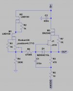
470R Kiwame 2W.What value are you using for the Rmu on the 10Y preamp.?
It's good up to 35-50mA (depending of the "lower" JFET type and saturation current).
I use J310 -39mA saturation current- at 30mA.
Attachments
The PCB is for the gyrator part of the 01A preamp. It's fairly small, but very necessary! The rest would be point to point.
Thx Andy.
Andy,
Do you know if Ale is getting messages? I filled out the form on the web page for the gyrator board, but did not get an answer? I also PM him from here and did not get an answer?
Give him time. He travels with his work. May not be at home. He tends to catch up in binges of activity.
Hi Bela,I also use in my 801 preamp J310 (and 1kV depletion MOSFET) in Ale's gyrator.
I prefer higher (25-30mA) anode current.
The tone -IMHO- "smoothens" about 25mA (I mainly use graphite anode 801s with moderate -7..8W- dissipation). The "steel" plate tubes (10, 10Y, 801 a etc.) "requires" higher anode current (in my 841-10Y-801a PSE amplifier I use this tubes at 30mA).
In this region -if the tube is in good working condition- the 3th distortion spectrum line is decreasing a little (according to my measurements), second is dominated (at line levels), so overall tone is become cleaner.
It's my experience, in my system, appropriate for my taste, so strongly subjective.
Did your gyrator worked properly from the start? I am trying Ale's gyrator with DN2540 and J310 and I can't adjust the plate voltage. The LND150 CCS works fine and I can adjust the reference. I use a bench HV supply, and as I increase the b+ the plate voltage increases with B+.
I can use a little help.
Thank you,
Radu
Hi Bela,
Did your gyrator worked properly from the start? I am trying Ale's gyrator with DN2540 and J310 and I can't adjust the plate voltage. The LND150 CCS works fine and I can adjust the reference. I use a bench HV supply, and as I increase the b+ the plate voltage increases with B+.
I can use a little help.
Thank you,
Radu
Hi Radu,
Now I use in my 801 preamp - quasi - fix B+ (simple CLCLC) and gyrators with J310 without any problem.
I tested this gyrator scheme with both (J310 and DN2540) FETs (and 01N100D a "upper" FET) in my test apparatus, but only with regulated B+ (Tomchr's MaidaII regulator).
Soon (at evening -European time- ) I will test it with variable power supply and will inform you.
p.s. I use higher reference voltage -aka greater resistor: 300k), than Ale.
- Status
- This old topic is closed. If you want to reopen this topic, contact a moderator using the "Report Post" button.
- Home
- Amplifiers
- Tubes / Valves
- DHT line stage 26, 01a or 101d