If you have not done so already download PSUD and simulate your power supply.
PSUD2
I would recommend changing the load resistor to the appropriate current value and also playing with a stepped load to see how your supply reacts to a change in load.
And then read a lot about what others have done with PSUD. There is much to learn and it is a very valuable tool.
ray
PSUD2
I would recommend changing the load resistor to the appropriate current value and also playing with a stepped load to see how your supply reacts to a change in load.
And then read a lot about what others have done with PSUD. There is much to learn and it is a very valuable tool.
ray
By the way don't forget to include a bleeder resistor that can cope with over your expected 500 volts or so. If necessary, use low voltage rated resistors in series.
Once you start testing, try getting a sense of how long the bleeder resistor takes to get the voltage stored in the caps down to zero.
ray
Once you start testing, try getting a sense of how long the bleeder resistor takes to get the voltage stored in the caps down to zero.
ray
I do also have a 10v CT AC transformer, if that could be adapted for the 5v filament supply. I'm concerned that I may not have room to fit it on the chassis though, at least not acceptably far away from the input section.
WHAT is the current rating of this transformer? With the 100uf oil caps + 4 transformers your chassis is getting rather crowded and heavy. It is not a big deal except you need to make it strong. cheers
Those PS layouts were done with PSUD2, great piece of software.
Switches, fuses, and bleeder resistors will all be present in the final design.
Heavy is no big deal, it's not going to be moved around a lot. The 10v transformer is rated at 10amps.
How might I lower the impedance of the PS section while still achieving minimal voltage ripple?
Switches, fuses, and bleeder resistors will all be present in the final design.
Heavy is no big deal, it's not going to be moved around a lot. The 10v transformer is rated at 10amps.
How might I lower the impedance of the PS section while still achieving minimal voltage ripple?
How might I lower the impedance of the PS section while still achieving minimal voltage ripple?
If you install another larger inductor to replace the second one you may not need the 2 dropping resistors. Although I am not sure what the B+ will be. You need to plug that into the psud. The first inductor needs to be more capable since it will be subject to full unfiltered voltage. If you need more voltage you can adjust the final B+ upwards by placing a small value cap in the first position making it cLCLC.
If your 10v filament transformer is center tapped you can use half of the windings for 5 volts.
cheers.
Last edited:
This is a highly contentious discussion. Low impedance in single ended power supplies means small capacitors (about 40uf max) for filtering and low DCR chokes . this will lead to more residual hum in B+ which will be more or less audible depending on the sensitivity of your speakers. I guess it is something you need to try and see if it is acceptable to you. cheersIt is going to be a mellow sounding amp with all the resistances in series...
I read that Class A like a low impedance power supply.
Last edited:
When I'm playing in PSUD2, it depends on where the B+ is going.
If transformer coupled output, your B+ flows through the output transformer. Any ripple there is going to be stepped down at the secondary. Say you have a 5k:8 transformer. The voltage ratio is 25:1, so even a few mV of ripple on the B+ becomes pretty tiny reflected on the secondary. You also have the AC impedance of the OPT primary in your favor.
If the B+ is going to an input stage (assuming single ended), you want to be a little more careful because ripple is magnified by the amplification of the stage. Again it is going to be somewhat mitigated, depending on your topology, but I try to minimize it as much as possible in the modeling. Real world performance is probably going to be worse. Luckily, input stages usually run at much lower current, so you can afford brute force filtering.
Consider some secondary filtering for your input stages. Something along the lines of CLC(output B+)RC(input B+) can work out well, space permitting.
There is a way of calculating the ripple in db, the noise floor and the ratio to output.... all this is garbage, for real there is way much more going on in the amplifier.
When you do your power supply design properly with reasonable voltage drop 5 to 10 mA is not a concern, in a tube amp there is greater contributors to the ripple: Heaters, Induction of the wires, Radio pick up.
Feedback will get rid of the most annoying 60hz and 120hz artifact picked up along the amplifying circuit.
Nice post Sodacose, the output transformer is a huge divider of B+ ripple.
Suggestion for Canadatubedude: instead of resistors in serie to lower the B+ to desired levels, find a transformer which has a lower VA. If you need to lower the voltage place high quality resistors to the ground, serie resistance is a nice thing in a phono stage with 1 mA , with a KT150 tube you are killing the sound because the transformer will never be able to supply the current demands through the resistance, consider 50 Ohm as the higher value for a choke resistance, and get a nice huge cap
Update
Wow thanks, those two posts are very informative. So <1mV ripple isn't really necessary, at least for the output stage. I'll take another stab at the PS design and go for less resistance.
I've already purchased the PT (Hammond 378CX) so I'm stuck with it.
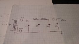
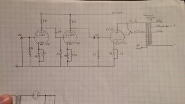
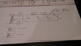
Here's a rough circuit I've drawn out. I haven't included values, I'm hoping you people can help me out with this.
Wow thanks, those two posts are very informative. So <1mV ripple isn't really necessary, at least for the output stage. I'll take another stab at the PS design and go for less resistance.
I've already purchased the PT (Hammond 378CX) so I'm stuck with it.
Here's a rough circuit I've drawn out. I haven't included values, I'm hoping you people can help me out with this.
Attachments
- Status
- This old topic is closed. If you want to reopen this topic, contact a moderator using the "Report Post" button.
- Home
- Amplifiers
- Tubes / Valves
- KT150 SE based on Mikael's KT88 Schematic