Better explanation here.
Powering Your Radio Safely with a Dim-bulb Tester
I bumped up to a 75W bulb (biggest I got right now) and it seems to settle in better. Going to get a 100W bulb to allow a little more current through - I actually think I may have a working amp as I get all five tubes glowing (slightly) now but will see what happens on a 100W bulb test. Fingers crossed....
Better explanation here.
Powering Your Radio Safely with a Dim-bulb Tester
That's a pretty good explanation.
The last paragraph is a bit confusing, where Mr Nelson says:
In contrast, a dim-bulb tester doesn't change the supply voltage. However, by putting a light bulb in series with your device, it limits the amount of current supplied to your device, thus reducing the risk of damage if there is a power supply problem, etc.
It's true that the dim bulb doesn't change the voltage coming into the combination of bulb tester and amp - the 'supply'.
However, it does change the voltage presented to the amp, since there's a voltage drop across each of the 'resistors' in the circuit (bulb + amp). Changing the bulb resistance (by switching to a different watt rating bulb) will change the voltage across the amplifier AC input (This all assumes the amplifier isn't a dead short, in which case there's no voltage drop across its AC terminals...)
Chris:
Well, I know it's 2018, and we are living in a state of 'altered reality' in many ways, but two absolutely different answers to the same question are seldom both correct.
Anatoliy actually wouldn't give an answer to NavyDiver about where to connect the chassis ground wire to the PCB, but he told me that absolutely the correct spot for that connection to the chassis is the negative ('ground') end of the 2nd filter capacitor.
You agree with that, I guess.
Morgan Jones says it's at the input jack.
Merlin Blencowe says it's at the input jack.
So it does seem that there is a difference of opinion (not fact?) on this point.
Most surprising to me was the comment from Anatoliy to me that I needn't bother with testing with a clip lead (a.k.a. experimenting to get 'data'). Where's the fun in that?
Last edited:
John; please ask Morgan Jones, if my live sound console has more than 50 of input jacks, more than 20 of output jacks, all of them can be wildly interconnected through outboard gear, which input jack must be connected to the chassis? And why despite of 16 channels with up to -74 dB sensitivity it does not hum at all when amps of our venerable Gurus with 0 dB sensitivity are afraid of ground loops, and hum like a hell?
John; please ask Morgan Jones,.......
When elephants fight, it is the grass that suffers.
Don't put me in the middle of this!!
Don't put me in the middle of this!!
I am pretty sure, instead of fighting he will explains you, that as soon as he has a star ground at the common point on the clean filter cap, and dirty currents through the wire from an input socket to this point do not flow, it does not matter in which point to ground this wire.
Now, why I have absolutely no hum in the console, despite of multiple voltage sources inside, such as +15 and -15 for opamps, +12 for relays, +12 for headphone amps, +27 for level indicators, +48V for phantom power, and no way to ground near one of input jacks?
Because the star ground is at the outputs of all voltage regulators, where they are maximally clean, and have minimal dynamic resistance between this star ground point and each voltage source.
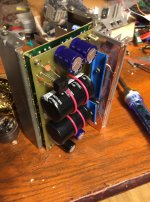
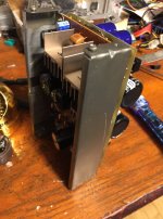
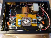
I am attaching pictures of the power supply from my live sound console. There are 2 boards, with rectifiers, filters, and first step voltage regulators, and the second one, with final voltage regulators. And only on the second board all grounds after filter and regulators are interconnected; it is the common ground.
In your amp it is much simpler: it is the second filter cap that is your common ground.
Attachments
Last edited:
There is no solder pad (hole) in the PCB right next to the negative lead of the 2nd filter cap, as far as I can see from the pictures posted by NavyDiver.In your amp it is much simpler: it is the second filter cap that is your common ground.
Should he try to solder a wire around the cap lead, or use one of the nearby unused solder points on the PCB, for his connection to the chassis?
Attachments
You are a lot more patient than I am!On to the next step - audio testing (not holding my breath but hopeful)
Get those cheap speakers and a source hooked up and let's hear it!
Hi VictoriaGuy,
I agree that you take the ground point of the power supply where you would have minimal noise current. That ground point can be located right where the input jacks come into the chassis. It can also be in a different spot that you chose. In Anatoly's console example, you can't very well ground at the input jack (which one would you choose?). In that respect, he and I have similar experiences since I used to do recording studio service. The main point isn't where you have your star ground located so much as what is connected and what part of the power supply goes there. In the tube amplifier I just designed, my power supply ground is at the output of the second regulator that feeds the input stage. That ground has the least ripply current flowing in it. The CT from the HT secondary goes directly to the filter #1 common. From there the ground runs from stage to stage in the regulator until it hits the output of the regulator and from there it hits chassis ground. That ground just happens to be in the area of the power supplies on the chassis. I couldn't use the RCA input area for this ground unfortunately.
Do you have a copy of Morgan Jones? It's pretty much the standard reference for high quality tube audio equipment and I think we all have a copy. Same as RHB4, and I also have RHB3, plus a number of other well known tests on the subject. I have these in real paper format, they aren't PDF files. Of course I have more reference material in PDF format as well. The important point is that Anatoliy isn't saying the star ground doesn't go at the input jack entry into the chassis at all. It's just that he can't do that in some cases. The same thing I ran into this time. What he is saying, and I am hoping the message doesn't get lost somewhere, is that the ground from the power supply comes from the least noisy section of it. That does tend to be the second or third filter capacitor in many devices.
In the old days, certainly pre-1970's, it wasn't uncommon to see grounds connected to points all across the chassis. Just wherever a ground connection was needed. They would often use the ground tab on an octal tube socket! While those units work without oscillation (gross grounding problem usually), they certainly could have a lower noise floor.
I think that Doug Self has a lot to say about grounding in both amplifiers and preamps. He also designs recording consoles and may touch on the rational behind where those grounds should come together. That's yet another pair of text books for your shelf.
So no one is conflicting with any of those great authors. You just have to understand that you can't always ground at the input jack for various reasons. Also, taking the ground for the power supply from the least noisy part is a common held view.
It's 1:30 AM here. I'm heading to bed.
-Chris
Well the news is not good. I did the alligator clip thing and did tap into the neg terminal of the 220uF cap as well as other places. Here is the result of one such trial without a circuit ground to case. Power just went out here in a wind storm so on my cell. Good thing as I need a time out to take a deep breath and re-group. Here is what happened: YouTube
Last edited:
Thanks for taking the time to explain, Chris.
It's a topic where confusion is easy.
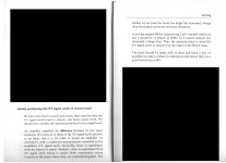
I do have a copy of Morgan Jones 'Valve Amplifiers 3rd Ed' and 'Building Valve Amplifiers'.
Both suffer from very poor indexes, but I was able to find on p134-135 of 'Building Valve Amplifiers' a section titled :"Ideally Positioning the 0 v signal earth to chassis bond" which seems to be what we are discussing here.
See attached pic.
I couldn't find a very extensive discussion of this (difficult for beginners) topic anywhere else in Morgan Jones'.
BTW, I have only a very slight experience with sound equipment, but aren't ground lift switches pretty common in that gear?
It's a topic where confusion is easy.
I do have a copy of Morgan Jones 'Valve Amplifiers 3rd Ed' and 'Building Valve Amplifiers'.
Both suffer from very poor indexes, but I was able to find on p134-135 of 'Building Valve Amplifiers' a section titled :"Ideally Positioning the 0 v signal earth to chassis bond" which seems to be what we are discussing here.
See attached pic.
I couldn't find a very extensive discussion of this (difficult for beginners) topic anywhere else in Morgan Jones'.
BTW, I have only a very slight experience with sound equipment, but aren't ground lift switches pretty common in that gear?
Attachments
There is no solder pad (hole) in the PCB right next to the negative lead of the 2nd filter cap, as far as I can see from the pictures posted by NavyDiver.
Should he try to solder a wire around the cap lead, or use one of the nearby unused solder points on the PCB, for his connection to the chassis?
Just resolder the center tap of the secondary from the transformer to the 1'st cap that is before the choke, it would be enough (I hope).
I just watched your video.Here is what happened: YouTube
First! BE careful to check that the HV caps are discharged completely before touching anything under the chassis.
Use your meter to check the B+ (HV) voltage at the caps before poking around in there with your fingers!
What happens with the shorting plugs in the input jacks?
It sounds to me like oscillation which will probably happen even if the input is shorted.
Is the '0' speaker terminal connected to the circuit ground? (not chassis).
It's a windy night here, blowing 30 knots everywhere. My power went out for a minute as well. UPS on the computer is working.
Last edited:
Responses appended in red.I just watched your video.
First! BE careful to check that the HV caps are discharged completely before touching anything under the chassis.
Use your meter to check the B+ (HV) voltage at the caps before poking around in there with your fingers! Will do - still waiting for parts from mouser to build my cap DIY discharge tool.
What happens with the shorting plugs in the input jacks?Didn't get that far before the power went out (most of the night)
It sounds to me like oscillation which will probably happen even if the input is shorted. What causes oscillation?
Is the '0' speaker terminal connected to the circuit ground? (not chassis). Yes via the coax wire that goes to the volume switch and then to the 6N9P octal sockets. The grounds ultimately go into the PCB common circuit ground.
It's a windy night here, blowing 30 knots everywhere. My power went out for a minute as well. UPS on the computer is working.
Power out here in Colwood (just off Metchosin road) most of the night. I mostly use laptops these days which are mostly impervious to outages except the connectivity
I could have tethered my phone but I was pretty much done at that point - needed a break to re-group
Last edited:
Responses appended in red.
Very painful to use and edit in this forum with a smart phone I might add. Hopefully this forum gets with the times sometime soon and provides a mobile interface version of their site for people on the go like other forums I participate in do. Just a thought for the admins
I HOPE NOT!!!Very painful to use and edit in this forum with a smart phone I might add. Hopefully this forum gets with the times sometime soon and provides a mobile interface version of their site for people on the go like other forums I participate in do. Just a thought for the admins
My brain is still capable of comprehending a full screen of information, and I can type properly on a real keyboard.
No problem at all getting the forum to work using a computer.
Many forums have been ruined by going to 'phone mode' or even worse...Facebook.
Sorry- Off topic - there's a sub forum for these discussions.
Responses appended in red.
Please use the reply box for responses - when you include your answer 'inside' my previous message, it is not available for me to comment.
I HOPE NOT!!!
My brain is still capable of comprehending a full screen of information, and I can type properly on a real keyboard.
No problem at all getting the forum to work using a computer.
Many forums have been ruined by going to 'phone mode' or even worse...Facebook.
Sorry- Off topic - there's a sub forum for these discussions.
The two can co-exist as it does on most sites (even mine) so no fears (the site automatically senses whether you are on a mobile device or a home computer and brings up the appropriate interface friendlier to that format. Google Chrome even lets you hot swap between modes as the mobile mode is usually a bit stripped down. - to the admins, try it you may like it): Copper Collar DJ and VJ Services
Last edited:
- Home
- Amplifiers
- Tubes / Valves
- Boyuu EL34 A9 Tube Amp