Дмитрий, приветSorry, some wirds about schematic and tubes.
Some days ago I also bought China case Beyuu.
But I'm looking for 300B and 6C4C ( Russian analog 6B4G)

The case is good, but there is no place for inductor 3H with 10-20 Ohm, it's like power transformer in size.
")
Если хотите прибавки в мощности можно попробовать на кт 66 или 88.
300 не популярная лампа , если для экзотики в коллекцию это допустимо.
Какие выходные трансформаторы вы приглядели ��
English, please.
You can't get more output power from the same power transformer, you already fried one without even 66 or 88. 300B is a gorgeous tube, one of the best power tubes ever designed for audio. But it would require completely different voltages. The chassis is made of stainless steel, extremely hard to drill.
You can't get more output power from the same power transformer, you already fried one without even 66 or 88. 300B is a gorgeous tube, one of the best power tubes ever designed for audio. But it would require completely different voltages. The chassis is made of stainless steel, extremely hard to drill.
Last edited:
OK,sorryEnglish, please
Hello ,
I'm not going to use kt88.
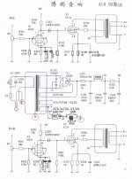
Dmitry asked about the circuit on the lamp 300.
my transformer caught fire due to the interturn short-circuit of the transformer wire; overload has nothing to do with it.
Chinese 6P3P requires 900 mA for heater, kt66 requires 1.27A, kt88 requires 1.6A.
6С4С requires 1A current for filament. But it needs such a voltage swing to be driven that a single 6Н1П stage can not deliver. Let's assume it is biased to 45mA at 300V voltage. That means Dmitry would need also -50V source for bias under the chassis, and some additional thingy to drive 6N1P to output 100V peak to peak. It can be some opamp, for example. It is doable, actually, while the suggestion to use KT66 or KT88 is not so wise.
Edit: oops, sorry, my bad. The chassis was made to accommodate a pair of Chinese 6P9P tubes right? So, no need for an opamp, 2 stages of 6P9P are enough to drive 6C4C, but still -50V is needed for bias. It can be taken from the same transformer using 2 SS diodes like 4007 and a voltage divider with a filter capacitor.
Last edited:
Do you think the A10 scheme is self-sufficient,It can be taken from the same transformer using 2 SS diodes like 4007 and a voltage divider with a filter capacitor.
Or is it worth looking for a scheme for EL34 from famous brands?
Attachments
quite right.As far as I know, the original transformer is center tapped? No?
Do you think the circuit needs some work on the EL34 lamp?
 .
.

I have found nothing on how the circuit ground arrangement is made. Was assuming that the screws holding the PCB were binding the circuit ground to the chassis or it was simply designed to marry up all the circuit grounds to be at the same potential. This is why I was planning to ramp up the power slowly with the variac/dim bulb tester combo if that makes any kind of sense? What is the purpose of the shooting RCAs? Are they used just to evaluate base circuit noise with no source input?Power transformer bolt is a pretty common spot to attach a safety ground - it's what I usually use, though I think the 'standard' requires a dedicated bolt for that purpose.
Or are you talking about where the 'circuit ground' attaches to the chassis...if at all....?
I don't have the A9 schematic handy.I have found nothing on how the circuit ground arrangement is made.
Have a look at the A10 schematic that LongRoad posted recently.
It shows 3 attachments to 'chassis ground':
-the 'green wire' from the AC IEC jack
-the transformer- grounded via the bolt if the paint is penetrated
-the place where the circuit ground (at the heater 'artificial center tap- 100R resistors) connects to the chassis via a resistor and cap in parallel.
This would be a reasonable scheme to follow, IMO.
Note that the 100R resistor connecting to the chassis has to be hefty enough to pass 'fault current' long enough for the house breaker to trip, so at least 2-3W rating. Or you could use a couple of higher value (250R?) resistors in parallel.
Attachments
Using the dim bulb (and Variac) is a good idea - if you have a short, the bulb will be bright.This is why I was planning to ramp up the power slowly with the variac/dim bulb tester combo if that makes any kind of sense?
More commonly in my builds, problems with circuit 'grounding' cause humming which doesn't show up until speakers (or scope) are attached to the output terminals.
'Open' inputs sometimes can act like wire antennas picking up noise from nearby sources like dimmer switches and switching power supplies for LED lamps, etc...What is the purpose of the shorting RCAs? Are they used just to evaluate base circuit noise with no source input?
Guitar amps use shorting jacks to prevent this problem. If you've ever plugged a guitar cable into an amp and then touched the end with your finger, you will have heard the noise.
The shorting plugs keep that noise from interfering with your troubleshooting.
the transformer is not grounded using the mounting bolt, the mounting bolt goes to the common wire.I don't have the A9 schematic handy.
Have a look at the A10 schematic that LongRoad posted recently.
It shows 3 attachments to 'chassis ground':
-the 'green wire' from the AC IEC jack
-the transformer- grounded via the bolt if the paint is penetrated
-the place where the circuit ground (at the heater 'artificial center tap- 100R resistors) connects to the chassis via a resistor and cap in parallel.
This would be a reasonable scheme to follow, IMO.
Note that the 100R resistor connecting to the chassis has to be hefty enough to pass 'fault current' long enough for the house breaker to trip, so at least 2-3W rating. Or you could use a couple of higher value (250R?) resistors in parallel.
The winding screen is grounded in the power transformer.
I do not know how to say exactly in English, in the transformer between the primary and secondary windings, a shield winding or a layer of copper foil is made,
its ground.
the transformer is not grounded using the mounting bolt, the mounting bolt goes to the common wire.
The winding screen is grounded in the power transformer.
I do not know how to say exactly in English, in the transformer between the primary and secondary windings, a shield winding or a layer of copper foil is made,
its ground.
Perfectly clear; thanks for the correction.
In the A10 there is a separate wire for the transformer shield and that's what is clearly shown connected to the chassis on the schematic. My mistake!
Note that the 100R resistor connecting to the chassis has to be hefty enough to pass 'fault current' long enough for the house breaker to trip, so at least 2-3W rating. Or you could use a couple of higher value (250R?) resistors in parallel.
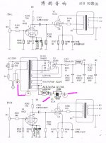
Do not do that. Instead, ground the negative end of C302 filter capacitor.
quite right.
Do you think the circuit needs some work on the EL34 lamp?
View attachment 722193 . View attachment 722194
There is a saying, "Нет предела совершенству". It will work as is, but I saw some kits on eBay with a better schematic using the same number of tubes.

Perfectly clear; thanks for the correction.
In the A10 there is a separate wire for the transformer shield and that's what is clearly shown connected to the chassis on the schematic. My mistake!
So I gather I don't need to ground the the power transformer to chassis - this is already done in the guts of the thing? I have shaved the paint down to bare metal on the top right transformer bolt in my red circled photo from post #539. That is where I have the IEC green wire attached to right now. I show no other chassis ground on the schematic that came with unlike the A10 variant:

I found this one online in this thread somewhere and it seems much better (although I did have to refer to both:

There was a conversation earlier in this thread where Wavebourn pointed out that it was a bad idea to connect more than one of the transformer bolts (electrically) to the chassis. You should wait for his comment on the transformer issue.So I gather I don't need to ground the the power transformer to chassis - this is already done in the guts of the thing? I have shaved the paint down to bare metal on the top right transformer bolt in my red circled photo from post #539. That is where I have the IEC green wire attached to right now. I show no other chassis ground on the schematic that came with unlike the A10 variant:
My understanding is that the 'shield' inside the transformer is not for safety in the case of an accidental short. I would connect both the shield and the transformer 'body' to the chassis, but my habit may be incorrect.
I don't understand.Do not do that. Instead, ground the negative end of C302 filter capacitor.
Are you saying that a direct connection to the chassis (not using the resistor and cap 'isolation' idea) is better, that the C302 filter cap should be connected to the chassis directly....
or:
that instead of connecting the chassis ground via the resistor/cap at the heater ground, it's better to connect it (still using the resistor/cap) at C302?
I agree that the heater CT is not the obvious place to connect to the chassis.
I'd think that in a 'kit' this would have been worked out?
One problem may be which holes in the ground circuit of the PCB are available.
In my home builds, sometimes I've used a test wire (alligator clips) to compare different ground points to get the one with the least noise.
This is the amplifier circuit with feedback that you showed.It will work as is, but I saw some kits on eBay with a better schematic using the same number of tubes.
I assemble an ultra-linear amplifier with straight mounting parts.
There was a conversation earlier in this thread where Wavebourn pointed out that it was a bad idea to connect more than one of the transformer bolts (electrically) to the chassis.
No, I did not say that. I said, that bolts have to be insulated from the transformer bell. That's it. One bolt can be connected to the bell to ground it, it would not cause a shorted loop. If you add nuts between the chassis and the transformer for air flow, the grounding lug will be tightly squeezed between 2 nuts, that is fine for me, however not for UL.
- Home
- Amplifiers
- Tubes / Valves
- Boyuu EL34 A9 Tube Amp