Hi Benman
A .subckt EL81 web research delievers this website:
paengdesign | paengdesign
I don't know how good the model on this website is, but I think it's worth a trial.
all the best, Adrian
I determined what this model is for. It is for type E81L, not EL81. The E81L is a long life small signal pentode designed for use in telecom equipment. The EL81 is a horizontal output tube designed originally I believe, for 405 line sets. Totally different beasts. It would have been nice if the individual at paengdesign had labeled it properly, but beggars can't be choosers.
So my original question still stands, does anyone have an EL81 model?
benman94,
do you have the means to measure tube curves or at least some working points of an EL81 sample?
I ask because the found EL81 / 6CJ6 datasheets doesn't contain any information about g1 current at positive Vg1.
Even when actually not intended by its inventors, todays applications (especially overdriven guitar stages) may show positive Vg1 peak voltages - and a model of mine shall deliver usable Ig1 values.
So, what are your possibilities?
all the best, Adrian
benman94,
do you have the means to measure tube curves or at least some working points of an EL81 sample?
I ask because the found EL81 / 6CJ6 datasheets doesn't contain any information about g1 current at positive Vg1.
Even when actually not intended by its inventors, todays applications (especially overdriven guitar stages) may show positive Vg1 peak voltages - and a model of mine shall deliver usable Ig1 values.
So, what are your possibilities?
all the best, Adrian
No method currently, but I am waiting on a uTracer, so I should have a method shortly.
For my intended application, I am running it using the stock Class B1 (really more deep AB1) operating point. 200 volts on the plates and screen grids, -32 volts fixed bias, grids never driven positive, into 2.5 kohms.
I just wanted a good model so I could more easily work out practical operating points for UL and with a tertiary feedback winding for the cathodes. I rather like the tube, but it really needs a fair bit of local feedback in the output stage to tame the pentode nastiness. An EL84 it ain't.
As an aside, I read through your 40 page treatise on vacuum tube modeling this afternoon with tremendous interest, particularly your pentode model.
Hi,
I downloaded "Ayumi_LTspice.zip (New 06/29/2018)". Where should I put the *.inc files on my disk? And what should I change in LTspice's Control Panel? I run the latest version XVII (x64) (Nov 7 2019).
Is there a LTspice "for dummies somewhere", just to get started? So far the F1 help is not very helpfull when working with tubes.
Regards, Gerrit
Last edited:
Is there a LTspice "for dummies somewhere", just to get started? So far the F1 help is not very helpfull when working with tubes.
Regards, Gerrit
Go to youtube -- there are many videos of 5 minutes or less which explain the basics -- and the production values are high given that they were produced by Linear Tech.
You might want to start with YouTube which discusses adding third party models.
No method currently, but I am waiting on a uTracer, so I should have a method shortly.
Hi benman94
Oh, you get a uTracer - congratulations ;-).
To get the g1 current measured, a possible way may be like this:
- connect g2 and plate ("triode mode")
- connect g1 to the uTracer g2 channel
- 0 to 8V in 2V steps for g1 would be fine (if possible)
And of course it would help to select out of a couple of tubes that sample which is closest to the datasheet
thanks,
Adrian
My intention, once I get the tracer sorted out, is to use a fair number of EL81s from different manufacturers and then from that, create a simple weighted average of the several tubes for plate and grid characteristics. That should give a result extremely close to the curves as found in the datasheet, while also accounting for considerations in the construction of the actual valves. Vacuum tubes in particular seem to rarely match the curves given in the datasheets all that closely.
Hi benman94
Oh, you get a uTracer - congratulations ;-).
To get the g1 current measured, a possible way may be like this:
- connect g2 and plate ("triode mode")
- connect g1 to the uTracer g2 channel
- 0 to 8V in 2V steps for g1 would be fine (if possible)
And of course it would help to select out of a couple of tubes that sample which is closest to the datasheet
thanks,
Adrian
Ron's Lab Notebook Item 9 "Build a Better Grid Loop" might have some hints.
FWIW, I wouldn't build the UTracer "Stock" (i.e. 300V)-- use the parts Ron recommends for the 400V version and calibrate accordingly. Elsewise you will wind up de-soldering a lot of resistors. The only part you might not have in your parts cabinet are the new transistors.
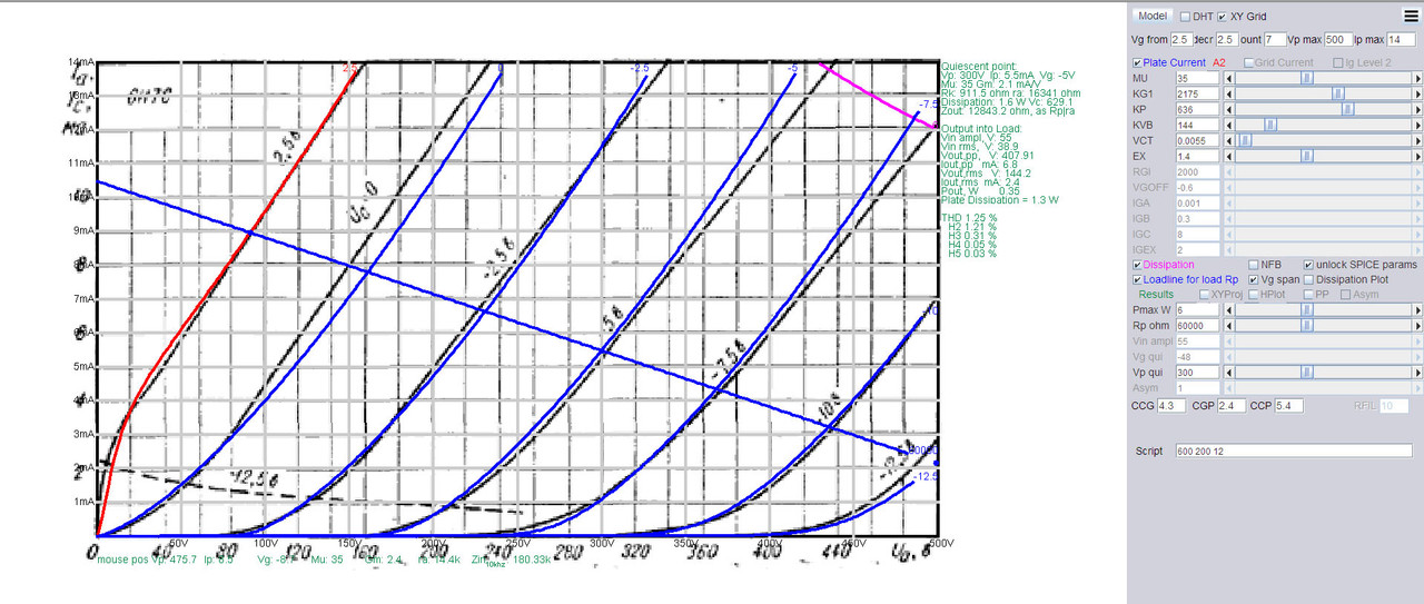
My model for Russian double triode 6N7S (6Н7С), made using paint tools. Not perfect, I know, but I can't make it better:
Code:
.SUBCKT 6N7S 1 2 3 ; Plate Grid Cathode
+ PARAMS: CCG=4.3P  CGP=2.4P CCP=5.4P RGI=2000
+ MU=35 KG1=2175 KP=636 KVB=144 VCT=0.0055 EX=1.4
* Vp_MAX=500 Ip_MAX=14 Vg_step=2.5 Vg_start=2.5 Vg_count=7
* Rp=60000 Vg_ac=55 P_max=6 Vg_qui=-5 Vp_qui=300
* X_MIN=258 Y_MIN=241 X_SIZE=1132 Y_SIZE=638 FSZ_X=2578 FSZ_Y=1458 XYGrid=true
* showLoadLine=y showIp=y isDHT=n isPP=n isAsymPP=n showDissipLimit=y
* showIg1=n gridLevel2=n isInputSnapped=y
* XYProjections=n harmonicPlot=n dissipPlot=n
*----------------------------------------------------------------------------------
E1 7 0 VALUE={V(1,3)/KP*LOG(1+EXP(KP*(1/MU+(VCT+V(2,3))/SQRT(KVB+V(1,3)*V(1,3)))))}
RE1 7 0 1G  ; TO AVOID FLOATING NODES
G1 1 3 VALUE={(PWR(V(7),EX)+PWRS(V(7),EX))/KG1}
RCP 1 3 1G   ; TO AVOID FLOATING NODES
C1 2 3 {CCG} ; CATHODE-GRID
C2 2 1 {CGP} ; GRID=PLATE
C3 1 3 {CCP} ; CATHODE-PLATE
D3 5 3 DX ; POSITIVE GRID CURRENT
R1 2 5 {RGI} ; POSITIVE GRID CURRENT
.MODEL DX D(IS=1N RS=1 CJO=10PF TT=1N)
.ENDS
*$
6BN6 model
Hi all the community and my wishes of the best for all folks here.
I want to know if anyone has a more or less accurate model for the 6BN6 tube (including the input from both grids, limiter and signal). It is for a timer I'm designing.
Many thanks in advance.
Hi all the community and my wishes of the best for all folks here.
I want to know if anyone has a more or less accurate model for the 6BN6 tube (including the input from both grids, limiter and signal). It is for a timer I'm designing.
Many thanks in advance.
6AG5 Pentode Model
Hi all
Happy New Year!
Here's the model for 6AG5 I developed after tracing the curves using eTracer.
6AG5 pentode – Bartola(R) Valves
Hope it's useful
Cheers
Ale
Hi all
Happy New Year!
Here's the model for 6AG5 I developed after tracing the curves using eTracer.
6AG5 pentode – Bartola(R) Valves
Hope it's useful
Cheers
Ale
Hi all the community and my wishes of the best for all folks here.
I want to know if anyone has a more or less accurate model for the 6BN6 tube (including the input from both grids, limiter and signal). It is for a timer I'm designing.
Many thanks in advance.
Just from an academic standpoint, I would love to see that model as well!
What a neat tube!
- Home
- Amplifiers
- Tubes / Valves
- Vacuum Tube SPICE Models