If,
You have 2 resistors in parallel with 54V across them..then you can say that you have one with 54V across it so 54/680=0.079 X 54v = 4.2...
So whats the wattage across each one? If they are 2watt resistors?
Yes they are sharing the current..that would be 54/340=0.158 X 54=8.57..(total)
If you reduce the Idle current of the tubes they will run cooler..
Do you have a drawing of the PSU you are using? so we can see what you are doing..are you dropping voltage for the power tubes with the resistors..if you are you will get sag.
Regards
M. Gregg
Last edited:
The PSU is standard GZ34 setup with CRC.... first cap is 50uf and I've discovered that the second cap is 220uf
I'm just ordering a 14 Watt 5% Wire-wound Resistor 470 ohms now which seems to drop the volatge to around 300V.... this goes straight to the CT primary of the OPT
cheers
I'm just ordering a 14 Watt 5% Wire-wound Resistor 470 ohms now which seems to drop the volatge to around 300V.... this goes straight to the CT primary of the OPT
cheers
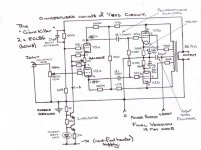
Also the voltages on the schematic above were obtained when I used the 2 x 680R in parallel in the supply. Giving a B+ of approx 310V
I want to put a slightly larger value of R in the supply to hopefully bring down the current drawn by the valves and reduce heat a little
I also have awful distortion / saturation at half volume so I have decided to introduc the GNF from 15ohm tap back to grid in diff amp. Just ordered 180K resistor and 22pf cap for this purpose, have attached schematic to show what this will look like, I ve increased the value of R as I am using the 15ohm tap and Ian used 4ohm tap in his schematic
Stuart
Remember,
You can buy a 15watt soldering iron....there is not much difference..
This is not about sinking 8W in a resistor..it would be better dropped in two stages..if thats what you want to do...Is this voltage drop for one channel? or is it sinking for two channels...
Here is a though for you...if you dropped in more stages how hot would each resistor get? ie series not parallel..Your still going to get sag..
Its the bias you need to change.....not series resistors in the B+
I have to sign off now I'm sure someone will pick up
with you..
Regards
M. Gregg
Last edited:
Just for interest..
At the bottom of the page..B+ reducer//
http://www.geofex.com/Article_Folders/mosfet_folly/mosfetfolly.htm
Its another way to do it..
Sorry updated the link..have fun..
Regards
M. Gregg
At the bottom of the page..B+ reducer//
http://www.geofex.com/Article_Folders/mosfet_folly/mosfetfolly.htm
Its another way to do it..
Sorry updated the link..have fun..
Regards
M. Gregg
Just had a moment of doubt
Attached is a schematic with some my voltages in red
12.1V / 390R = 31mA
How am I drawing 156mA of current if 4 x 31 = 124mA
Doesn't that mean the triode section for the diff amp is drawing the rest which is 30mA / 4..... Thats 7mA each triode.... I think this is too much?
S
Each triode pair is drawing 1.25 mA, what the constant current supply feeds it.
Thanks... so surely the amp should only draw (4 x 31mA) 124mA for the pentode output.
The CCS supply is fed from another rail, not the B+
So, why, when I insert my DVM as ammeter into the B+ before it splits to the two OPT's do I get 156mA??
Where could the extra 30mA be going?
cheers Stuart
The CCS supply is fed from another rail, not the B+
So, why, when I insert my DVM as ammeter into the B+ before it splits to the two OPT's do I get 156mA??
Where could the extra 30mA be going?
cheers Stuart
Measure the current value into the CCS,
Collector of BC547..see what you have for each channel..subtract this from the B+ current the rest must be going through the OP tubes..
Measure the voltage across the cathode resistors on each output tube calculate the current add it to the current into the CCS how close is it to the B+ current value?
Are the currents balanced for the OP tubes? Are you sure the cathode resistors are the same/equal values..
If there is some current missing you need to know..there could be leakage somewhere..but don't go down that path until you are sure..ie the coupling caps if leaking could draw current and drop it across the grid resistor..however you would expect unbalanced currents in the OP tube cathodes.
With regards to the B+ reducer I posted you could use this with lower voltage drop and then leave enough to get the smoothing required for the B+ with resistor dropper..
Just mount the FET under the top plate..
Regards
M. Gregg
Last edited:
Other possible maybe..
Is one of the cathode capacitors leaking?
This may still show correct voltage across the cathode resistor...but the current might be greater..on that tube..this may show as current "in" on B+ does not equal current calculated using voltage across cathode resistor..Under these conditions you would have to measure B+ current into the tube anodes..so BE VERY Careful..
If it makes it easier to visualise then think of the cap leakage acting as a high value resistor across the cathode resistor<<parallel resistance..
Regards
M. Gregg
Last edited:
Thanks M Gregg & co,
I like the idea of the Mosfet/ Zener combo to drop B+. However, at this point in my education I would like to keep things as simple as possible in order for me to get a full understanding of what is happening in my amp. (Not there yet!)
So I think I am going to buy an 150R 10W resistor for the first smoothing...
It will then go GZ34 - 50uf - 150R - 220uf
I will then establish further dropping splitting the B+ and inserting one 390R 10W resistor per channel prior to it going to the CT of primary on each OPT.
The transformer is supposed to be 270 - 0 - 270 and i got 295Vrms from 0 to anode unloaded.
Once I have a B+ of approx 300V I will then re measure all currents as you guys have suggested.
Does my maths and component choice seem close for the PSU resistors?
S
The voltage drop on the PSU,
Is set by the current flow so only you realy know the value..
(Got to leave you some fun).. ..don't forget your discharge current..
The heat and placement of the components is impotant so keep them away from capacitors etc..Don't put a power resistor direct onto a Transformer connection or cap connection..it will probably melt the Tx connection..or over heat the cap..
The voltage on the power tx is probably regulation..unloaded..
Regards
M. Gregg
Is set by the current flow so only you realy know the value..
(Got to leave you some fun)..
..don't forget your discharge current..The heat and placement of the components is impotant so keep them away from capacitors etc..Don't put a power resistor direct onto a Transformer connection or cap connection..it will probably melt the Tx connection..or over heat the cap..
The voltage on the power tx is probably regulation..unloaded..
Regards
M. Gregg
Just a quick EG,
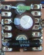
Note power resistor not direct on to cap..and distance from cap. The higher the wattage the resistor is dissipating the more you distance it..
Or mount it on the chassis away from other parts.. an easy way to lift tag board is put a large nut (loose fit bigger size)on the screw under the tag board to act as a spacer so its clear of the connections..
Then you always get an equal size spacer..its quick and idle/easy way to do it...
Regards
M. Gregg
Attachments
Last edited:
Thanks... so surely the amp should only draw (4 x 31mA) 124mA for the pentode output.
The CCS supply is fed from another rail, not the B+
So, why, when I insert my DVM as ammeter into the B+ before it splits to the two OPT's do I get 156mA??
Where could the extra 30mA be going?
cheers Stuart
Don't guess .... measure
You have 2 channels?
disconnect both.
Measure current from the PSU to one of them.
Measure what's getting into the transformer center tap. How much?
Then same with the other.
Are both the same?
Then on each channel measure what's getting into each plate.
Does it match what you read across same tube cathode?
Measuring beats guessing 10:0
Do I have to lift the transformer secondary center tap? I guess I do to place DVM as ammeter in between....
I'm guessing this will not account for the 6.3V and 5V rails? But it will account for any current drawn by the GZ34....
eg. If one channel is drawing 75mA then the CT will have a larger current draw?
and, is the 1mA CCS current provided by the 6.3V rail from which I've built my CCS supply or is it provided by the b+?
S
What kind of meter are you using?
The number one golden rule is..you don't measure from a distance...put the meter direct in line with the component in this case either the Op Tx B+ connection or the tube anode.. connect with it switched off power up and write down the value..power off and wait for discharge..remove and reconnect the meter and then check next connection..
If you measure from a distance you have no way of knowing if there are problems between the meter and other points in the circuit..
DC current measurement...with a meter that can take the DC voltage level..
REMEMBER NEVER EVER CONNECT YOUR METER ACROSS VOLTAGE MEASUREMENT POINT WITH IT SET TO CURRENT...ALWAYS RESET THE CONNECTION AND SETTING TO VOLTAGE AFTER THE MEASUREMENT TO PREVENT AN ACCIDENT..THE METER IS A SHORT CIRCUIT WHEN IN CURRENT MODE. SO IN CURRENT ITS IN SERIES WITH A LOAD NEVER ACROSS IT..
So you will always disconnect a wire to insert the meter for a current measurement..
Regards
M. Gregg
Last edited:
CCS,
Ok think about this...the B+ on the tubes anode has to flow back to supply or there is no circuit through the tube..so how does it get back to supply? (the other side of the B+)
Think about batteries in series...you have taken the ov rail negative..so how does the anode current get a circuit back to the other side of the B+?
The current would have to flow through B+ and negative rail to get back.
One side of the CCS supply must be common to the B+ ground correct?
Regards
M. Gregg
So,
When you put batteries in series does only one supply the current?
Answer no...voltage=pressure..current = flow..
So you could say when a circuit operates a current flows..when a circuit is off you can have voltage without current flow..ie its the pressure against a closed pipe..You cannot have a circuit in operation with just voltage and no flow<<current.
Regards
M. Gregg
Just for fun..
OK so what happens if you put a 10A supply in series with a 1 A supply..
The voltages are added...OK we draw 1A..all is well no problems..
We have a short the 10 A supply provides 10A of current which now flows through the 1A supply because they are in series..what will happen?
So now..think about a Tx winding which is thicker CSA? a high voltage low current winding or a high current low voltage winding..put them in series put a short on them..what will happen..
In the above case to protect both Tx's which do you rate the fuse for the highest or lowest current?
All good fun....
Regards
M. Gregg
Last edited:
- Status
- This old topic is closed. If you want to reopen this topic, contact a moderator using the "Report Post" button.
- Home
- Amplifiers
- Tubes / Valves
- Transformer bubbling