Grid stoppers need to be as close as possible to the valve base, with as short a length of wire on the valve side as possible - half an inch is too long! Other components can be further away, but you do need to think about stray capacitance at high impedance points and (possibly - although unlikely in an audio circuit) stray inductance at low impedance points.
Well having had no other use for credit cards I decided to cut one up with Scissors and I managed to splice it under the tag boards to give another few mm of insulation from the chassis.
Ran the transformer unloaded for a couple of hours with no heat issues and then reinserted all valves and started to listen to music again. The amp sounds amazing, however, the heat is back. One hour or two and the power transformer is too hot to touch. I also touched the PIO coupling capacitor which was also extelmley hot... AND I am sure it was vibrating with the music on. Could this be possible?
I will move the capacitors but I still think this amp runs real hot. The main metal chassis was salvaged from an amp that used ecl86 in PP. Therefore the placement of the valves, the output transformers and the power transformer was already fixed. Is it possible that my ecl86 (baby hueyish) setup would run hotter and therefore need more distance between components?
Also, Ian who generously posted the schematic for my amp used a global negative feedback from the 4ohm tap which he said I may not need. But he said that if I used it I would reduce the gain. I have plenty of volume spare on the knob as I only need turn it a quarter to get a decent volume. I wandered if I used the GNF and reduced the gain, would the amp run cooler? Or is my logic wrong?
Stuart
Hi Stuart, I would start by ensuring the thing is not oscillating. If you place an am radio near it you will know.
As for the coupling cap being hot, hmm seems odd. Your construction is certainly different but I wouldn't say bad. As DF96 says the only things you really need to have at the socket are stopper resistors. A lot of people say use carbon composition but I think this is nonsense based on old school beliefs. A modern carbon or metal film resistor has very little inductance, perhaps even bettering an old school carbon comp.
Anyway here is a link to some construction that I like. It must be said that for so called hi fi I would use different heater wiring:
The Champ CBA-20807 1000 Watt Amplifier - Part 1
Cheers Matt.
I have an amplifier test bed with a low current transformer to test new amplifiers.
It can only supply 2 amps and that is way below what it takes to blow up an output transistor.
Having said that I turned it on one day and the transformer started to grumble, I didnt realise that there was a short. After a minute the transformer started to bubble and I could smell it so turned it off quickly.
Luckily the transformer was OK and I have used it loads of times since.
I guess it must be the resin coat on the transformer wires that was cooking, bubbling and smelling.
It could be the transformer is cooked but you will only find out by measuring the output voltages off and on load.
Do you have sufficient air flow through the amplifier ? That would cause no end of problems.
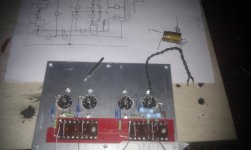
Well the valves are all surface mounted above the chassis as they were in the original amp, although the original amp had the valve sockets in a pcb type board which may have absorbed heat better.
What do people think about adding the GNF from the OPT 15ohm tap back to the grid of the Phase splitter?
Currently only the 3ohm tap is connected as I use this to drive my speakers, but I could connect the 15ohm tap back for GNF and this would reduce the rp (gain?) - would it also potentially reduce the heat if the amp had less gain in idle state?
Stuart
Just realised my bleed resistor was 22K which will be drawing 15mA between HT 310v and ground. This will be adding to my heat problem, can anyone recommend a better value? And what wattage would I need here?
And would lowering the B+ slightly (from 310 - 290V) have an effect on the heat?
And.... could I lower the heater voltage at all?
I need less heat!!
Stuart
And would lowering the B+ slightly (from 310 - 290V) have an effect on the heat?
And.... could I lower the heater voltage at all?
I need less heat!!
Stuart
If I put a 220K bleed in, what wattage will I need? Do I use ohms law to determine current ... 310V / 220000 = 1.4mA
Then do VA for wattage? 310 x .0014 = .434 W
Then multiply by factor of 3 for safety? making a minimum fo 1.5W resistor for bleeding?
And, any comments on whether lowering B+ by 20V will reduce heat from the valves? I need to get this amp to run cooler, considering drilling more holes in the sheet aluminium plate that the valve sockets are mounted in....
Stuart
Attachments
Whatever you use to reduce HT will dissipate some heat itself.
If you are running valves within their ratings and have reasonable air flow available to them then they will be OK. Valve equipment always runs hot. The main thing is to ensure that under-chassis components don't get cooked - especially electrolytics. If possible, don't put an electrolytic next to a power resistor. Maybe add some ventilation holes above any particularly hot items, and of course some entry holes underneath.
If you are running valves within their ratings and have reasonable air flow available to them then they will be OK. Valve equipment always runs hot. The main thing is to ensure that under-chassis components don't get cooked - especially electrolytics. If possible, don't put an electrolytic next to a power resistor. Maybe add some ventilation holes above any particularly hot items, and of course some entry holes underneath.
If I put a 220K bleed in, what wattage will I need? Do I use ohms law to determine current ... 310V / 220000 = 1.4mA
Then do VA for wattage? 310 x .0014 = .434 W
Yes, or any of these may help, depending on the parameters available...
I = V / R
V = I * R
R = V / R
P = V * I
or
P = V * V / R
or
P = I * I * R
And yes, a safety margin is always a good thing - three times for resistor power dissipation is a good starting point - you can increase the multiplier, but I would generally not go lower.
Hi,
220K use 2Watt or higher.. Also look at the working voltage<<<very important
Work out your wattage with 22k what are you dissipating? (Just for fun)
Have a look at the working voltage of 0.5Watt resistors..1Watt etc its very important you know this..there is more to a component than just value.
When an amp starts up the voltages can be very different and then settle after warm up..") ..the current will also be different..so you must take surge and charge into account. Also any possible fault currents before protection operates..some people design a component to fail causing a "safe fail".
..the current will also be different..so you must take surge and charge into account. Also any possible fault currents before protection operates..some people design a component to fail causing a "safe fail".
However its just important you look at working voltage for now!
Higher vales of discharge resistor "may" mean the B+ rail will take longer to come down after power off nothing wrong with this just be aware of it! The most important thing is to stay within the rated current of the Power Tx winding.
Regards
M. Gregg
220K use 2Watt or higher.. Also look at the working voltage<<<very important
Work out your wattage with 22k what are you dissipating? (Just for fun)
Have a look at the working voltage of 0.5Watt resistors..1Watt etc its very important you know this..there is more to a component than just value.
When an amp starts up the voltages can be very different and then settle after warm up..
..the current will also be different..so you must take surge and charge into account. Also any possible fault currents before protection operates..some people design a component to fail causing a "safe fail".However its just important you look at working voltage for now!
Higher vales of discharge resistor "may" mean the B+ rail will take longer to come down after power off nothing wrong with this just be aware of it! The most important thing is to stay within the rated current of the Power Tx winding.
Regards
M. Gregg
Last edited:
Have a look at this link maplin..
The 2Watt range sound good and they have a good working voltage
Metal Film 2W Resistor : Metal Film : Maplin Electronics
Now compare it to this 0.6watt..
http://www.maplin.co.uk/metal-film-0.6w-resistor-2162#specification
Working voltage always comes first ...the size may be limited by voltage rating...and the type you want to use.. High power wire wound look much bigger but the voltage rating may be to low. So always check before you use them..
Regards
M. Gregg
Last edited:
thankyou matt,
This is something I knew about 20 years ago when I was into electronics as a youngster. Alot of water has passed under the bridge since then and I've just realised that I sourced most of the components for this amp without doing that!! So thankyou for pointing it out. I am going to check, I think i picked all resistor values as 1/2 watt but overlooked the working voltages, I didn't go for the cheapest ones but still I need to check. I made sure all the capacitors were within working voltages but I forgot about the resistors.
I am going to be unsoldering a couple of the caps anyway to move them clear of other hot components. I am hoping to find why my amp is unable to run for more then an hour without the power transformer and components all being to hot to touch.
cheers again.. stuart
thankyou matt,
. I made sure all the capacitors were within working voltages but I forgot about the resistors.
cheers again.. stuart
Not Matt<<<
Nothing wrong with over spec components ie higher wattage..you get less chance of over load failure, working voltages are higher etc. You don't want a discharge resistor to go open (So higher wattage is OK)...The B+ (HT) will always seem to go down quickly due to the idle current of the OP tubes and still having warm heaters..its if the heaters fail and the B+ has no discharge path, thats when its going to get you when you least expect it..
The trick is to get B+ down as fast as possible without Transformer over load. So yes try 220K see how long it takes..
Just for interest low wattage cathode resistors go pop with a flash over in power tubes...a bit of a pain when you have to replace the resistor and fuse instead of just a fuse..
Regards
M. Gregg
Last edited:
Well, to begin with, you are absolutely *COOKING* it
The datasheet http://frank.pocnet.net/sheets/155/e/ECL82.pdf clearly shows that for >250V plate voltage (you have 300V) *maximum* plate dissipation must be kept below 5 Watts ... and you are dissipating 8 watts each
You must lower that idle current.
As a test, double the value of those cathode resistors and measure voltage across them.
We expect no more than 16 or 17mA *max* per tube, now we have 26 mA.
I'm amazed those tubes are not redplating .
Why do we use so few sockets for transistors?
pulling out a tube in a working amp usually does not result in magic smoke coming out.....
try doing that on a socketed transistor...
@jm fahey
Not using ecl82, I am using ecl86
@M.Gregg - sorry... never was very good at names. I have used what I had spare regarding the bleed R. I know have a very high wattage (22W) 33k first and then a (2W) 100K to ground. It seems to bleed almost as fast but then gets much slower then before for the final 10V... I seem to remember an exponential curve for capacitor discharge at school.
So I've drilled 6 x 8mm holes around the valve sockets, and I have moved some of the components so they are not so bunched.
I have placed an ammeter between final PS cap and OPT's and I get 156mA which I believe is perfect.
I have CRC smoothing from a GZ34 ... 50uf then (2 x 680R in parallel = 340R) then 100uf
These resistors are cooking, they are not small and at a guess must be 2W each ... i thought putting them in parallel would increase the power tolerance?
They are dropping 54V across them. Would it be a good idea to drop less voltage here and use dedicated high wattage droppers after the CRC?
If I run the tubes with less current, will this reduce the heat they put out? And is anyone able to tell me if I add the GNF from the 15ohm tap back to the diff amp if this will reduce heat also?
Stuart
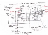
Just had a moment of doubt
Attached is a schematic with some my voltages in red
12.1V / 390R = 31mA
How am I drawing 156mA of current if 4 x 31 = 124mA
Doesn't that mean the triode section for the diff amp is drawing the rest which is 30mA / 4..... Thats 7mA each triode.... I think this is too much?
S
Attached is a schematic with some my voltages in red
12.1V / 390R = 31mA
How am I drawing 156mA of current if 4 x 31 = 124mA
Doesn't that mean the triode section for the diff amp is drawing the rest which is 30mA / 4..... Thats 7mA each triode.... I think this is too much?
S
- Status
- This old topic is closed. If you want to reopen this topic, contact a moderator using the "Report Post" button.
- Home
- Amplifiers
- Tubes / Valves
- Transformer bubbling