Ok, just for fun ... although it's a valid doubt ")
The "10 A supply" is a Voltage supply which can supply up to 10A
The 1A supply is also a voltage supply which can supply up to 1A
But actual current will depend on load.
How much will pass under short conditions?
It will depend on actual PSU construction details.
Are they current limited? (as in having some protective device)
Even if they are not, but very simple transformer>bridge>caps the 1 A rated one will presumably have 10X the internal resistance of the 10A rated one, so it will limit current anyway.
Will probably overheat and burn doing so, but definitely not pass 10A.
How much will it pass?
Insufficient data, we should know the voltages involved, internal resistance of each, etc.
True. Within the current capability of both supplies.Just for fun..
OK so what happens if you put a 10A supply in series with a 1 A supply..
The voltages are added...OK we draw 1A..all is well no problems..
This is wrong.We have a short the 10 A supply provides 10A of current which now flows through the 1A supply because they are in series..what will happen?
The "10 A supply" is a Voltage supply which can supply up to 10A
The 1A supply is also a voltage supply which can supply up to 1A
But actual current will depend on load.
How much will pass under short conditions?
It will depend on actual PSU construction details.
Are they current limited? (as in having some protective device)
Even if they are not, but very simple transformer>bridge>caps the 1 A rated one will presumably have 10X the internal resistance of the 10A rated one, so it will limit current anyway.
Will probably overheat and burn doing so, but definitely not pass 10A.
How much will it pass?
Insufficient data, we should know the voltages involved, internal resistance of each, etc.
What I explained above, the high voltage winding resistance will be the main limiting factor.So now..think about a Tx winding which is thicker CSA? a high voltage low current winding or a high current low voltage winding..put them in series put a short on them..what will happen..
The lowest one, of course.In the above case to protect both Tx's which do you rate the fuse for the highest or lowest current?
CoolAll good fun....
Pk, just for fun ... although it's a valid doubt
The so labelled "10 A supply" is a Voltage supply which can supply up to 10A
The 1A supply is also a voltage supply which can supply up to 1A
EDIT: But actual current will depend on load + internal resistance.
How much will pass under short conditions?
It will depend on actual PSU construction details.
Are they current limited? (as in having some protective device)
Even if they are not, but very simple transformer>bridge>caps the 1 A rated one will presumably have 10X the internal resistance of the 10A rated one, so it will limit current anyway.
Will probably overheat and burn doing so, but definitely not pass 10A.
How much will it pass?
Insufficient data, we should know the voltages involved, internal resistance of each, etc.
In the above case to protect both Tx's which do you rate the fuse for the highest or lowest current?
All good fun....
Regards
M. Gregg
True. Within the current capability of both supplies.Just for fun..
OK so what happens if you put a 10A supply in series with a 1 A supply..
The voltages are added...OK we draw 1A..all is well no problems..
This is the wrong approach.We have a short the 10 A supply provides 10A of current which now flows through the 1A supply because they are in series..what will happen?
The so labelled "10 A supply" is a Voltage supply which can supply up to 10A
The 1A supply is also a voltage supply which can supply up to 1A
EDIT: But actual current will depend on load + internal resistance.
How much will pass under short conditions?
It will depend on actual PSU construction details.
Are they current limited? (as in having some protective device)
Even if they are not, but very simple transformer>bridge>caps the 1 A rated one will presumably have 10X the internal resistance of the 10A rated one, so it will limit current anyway.
Will probably overheat and burn doing so, but definitely not pass 10A.
How much will it pass?
Insufficient data, we should know the voltages involved, internal resistance of each, etc.
What I explained above, the high voltage winding resistance will be the main limiting factorSo now..think about a Tx winding which is thicker CSA? a high voltage low current winding or a high current low voltage winding..put them in series put a short on them..what will happen..
In the above case to protect both Tx's which do you rate the fuse for the highest or lowest current?
All good fun....
Regards
M. Gregg
OK, I am slightly confused but this is helping...
The CCS is adding current flow to the circuit? Because they both need to return through the same ground?
So if one channel of amp is passing 75mA and the CCS 1mA is entering the cicuit at the cathode of the triodes then....
The current gets added to B+?
S
The CCS is adding current flow to the circuit? Because they both need to return through the same ground?
So if one channel of amp is passing 75mA and the CCS 1mA is entering the cicuit at the cathode of the triodes then....
The current gets added to B+?
S
The way the tag boards are mounted, they will easily create a short to the chassis - which has probably already happened...
Besides, those higher wattage resistors will fry the capacitors that are touching them. Not a good idea IMHO.
Rundmaus
Absolutely true on both counts. Plus the chaotic layout might encourage parasitics which will lead to oscillation.
The schematic shows a simple design that has been around for decades. There is no reason you can't make it work.
I would consider a new layout that allows for air circulation around the parts, easy access for test probes, and thought given to isolating components that might give rise to inductive or capacitive coupling. There is no need to make everything as compact as possible. Consider a circuit board (even a generic perfboard would work) or some old fashioned terminal strips. One of the beautiful things about 50s era amplifiers is that everything is spread out so that even gorilla hands can troubleshoot and repair it.
I even discovered I was at an age that I needed glasses whilst soldering that lot together
I have to wear two pairs of glasses plus use a magnifying glass to see what I'm doing on a circuit board. It doesn't stop me at all.
don't guess.. measure
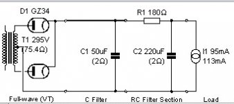
Ok, am building the new PS with a 50uf - 180R - 220uf
Then the plan is to split the B+ here for each channel. As I have the circuit open I thought I would put an ammeter in. I used a final dropper of 390R and connected one channel.... and I'm getting 100mA!! And I get 100mA when I repeat this on the other channel
Not good... I thought each channel would only draw 60mA
S
Er..
You only had one channel connected....so current drawn was not correct..
So only a guess but B+ was high..
You must keep the situation the same..when measuring one channel..
B+ is dropped across your resistors..so if you disconnect one channel and power up the current is different and the B+ will rise..Its only a guess because I can't see what your doing..
This is the difference with the Circuit with the FET,,,its not dependant on current drawn to drop the voltage...what will happen if one channel of your amp stops working to the other channel? B+voltage will change..what will that do to the OP tube bias?
you need to look very carefully at this situation..is it beacuse you only had one channel connected? Not both or is the bias way out?
Regards
M. Gregg
Last edited:
OK, thanks for sticking with me!
For some silly reason I thought the circuit would only draw what it needed, I forgot that ohms law says that if less current is drawn - more voltage will be created
I will reconnect the circuit with both droppers/channels and insert ammenter between one of them....
Also. I'm using a unitrend UT60 DVM.... I have been using the 10A setting on the DVM but I just downloaded the manual and it says not to test current if voltages exceed 250V
I'm very disheartened by this, does it mean I have to cease my testing?
S
Is it this,
http://users.tpg.com.au/users/p8king/files/ut60e.pdf
This is rated at 1000VDC...
Can you post the link to the manual?
Regards
M. Gregg
http://users.tpg.com.au/users/p8king/files/ut60e.pdf
This is rated at 1000VDC...
Can you post the link to the manual?
Regards
M. Gregg
Last edited:
It certainly is! (just pleased to be certain of something right now)
and this is copied from the manual
Never attempt an in-circuit current measurement where the
open-circuit voltage between the circuit and ground is
greater than 250V.
I really want to connect both channels and get the current values to each...
S
and this is copied from the manual
Never attempt an in-circuit current measurement where the
open-circuit voltage between the circuit and ground is
greater than 250V.
I really want to connect both channels and get the current values to each...
S
Uni-Trend Group Limited
There is a download link to the manual at the above page...
I know its rated at 1000V for measuring voltage, unsure about current
S
There is a download link to the manual at the above page...
I know its rated at 1000V for measuring voltage, unsure about current
S
Looking at what you have posted,
Your circuit is higher than 250V....it must be someting to do with insulation inside the meter....strage when the DC voltage is 1000VDC
So yes I would not use it to measure current..so how can you do it..
Use voltage measurement and put a Known resistor in place of the meter low value ohms then calculate the current from the voltage drop..so in effect your using a shunt..don't know how well it will work you will have to try it..
I always use Fluke meters...
Regards
M. Gregg
I have looked at the manual..
Thats what it says..I have never seen that low a voltage on the current range..its very strange Page 22..
I would not use it..unless you can use a shunt and measure the DC voltage and calculate..Its very strange
The only other thing I can think of is the internal fuse is not rated high enough (voltage) so it can't interupt a short circuit on voltages higher..It might be worth contacting them and see if you can use HV probes with internal fusing to over come this..or if this is not possible because the meter internaly cant tolerate the B+ on the current range..
My guess is its the internal fuse..however I would not use it as is...I would hate to think the insulation is no good on the current range.
If its the internal shunt that is not rated high enough your stuffed...
I have to sign off now..someone will pick up I'm sure..
Regards
M. Gregg
Last edited:
Thanks again for the help....
So never trust a multimeter that can't handle the voltage when taking current measurements....
My PSU is attached.... I connect this to the OPT's via one 390R in each channel...
I measured the voltage before and after the 390R for each channel
one channel was 333V dropping to 312V (21 / 390) = 54mA
other channel was 333V dropping to 310V (23 / 390) = 59mA
Now I am happier, I can't believe the DVM gave me 156mA, I've been putting this into Duncans PSU designer as a load and pulling my hair out as the results didn't match up..... They do now!!
I will be adding a final 47uf 450V cap to ground after each 390R.....
So I am back on track, have lifted the tag boards and drilled 6 8mm holes around the valve sockets for extra cooling. I have also moved some of the coupling caps out of the way to allow for extra cooling. I have also increased the bleed resistor and split out the dropper resistor...
All of this to reduce heat.... I will test tomorrow night and see how long it takes before the amp is untouchable due to heat!!
I'm dreading someone telling me that my valves are too close together.... I have 1.5inch between center to centre of one channel
and 2 inches between center to center (valves) of each channel.... In hindsight I would have moved the vlaves further apart .... is this going to cause my amp to only be useable for a few hours at a time?
S
Attachments
Last edited:
Anyway let's not lose the main focus: your amp is pulling *much* more than rated or expected.
That transformer is overheating.
Those tubes are overheating.
You'll have to solve that one way or another.
A resistor in series will lower voltage, no doubt, but will also radiate *heat*.
*Maybe* you should consider , in order of complexity:
a) increase cathode resistors.
I'd double them, remeasure, and then proceed swith some fine tuning, either increasing or decreasing their value, don't know beforehand, depends on what we measure.
b) rebuild it as a more "classic" amp, tried and true, no CC sources or any transistor or other SS stuff.
In this case I might also consider adding fixed bias so I can easily adjust it to taste simply turning a preset. Very convenient.
c) I'd go all the way and build a classic 2xEL84 amp there.
I have 2 LC meters, a USB and handheld.
I measured a SMPS transformer leakage inductance on them.
One gave 120uH and the other gave 60uH which were sort of what I was expecting.
However the SMSP kept dropping out with an over current fault.
Someone suggested making a series resonant circuit with a resistor and the transformer leakage inductance. I measured the resonant frequency and from that worked out the inductance to be 10uH !!!!! No wonder i was having problems.
Sometimes its better to read voltages across resistors than rely on a meter measurement of current.
Regards Valve distance..
The rule of thumb is that all tubes should be at least one tube width apart(Min) one and a half is better, one tube width between each tube..so you should be able to put another of the same tubes between any on the top plate.. In layout its always better to keep high gain and preamp tubes away from transformers and AC voltages..the mains Tx is a real pain if its by any high gain stages.. And preamp stages away from OP sections.
This is important..
The voltage of your B+ is set by the current drawn (VD across Resistors)
You have minimised this by using seperate droppers for each channel..however the VD across the 180 ohm will alter should one channel go open due to heater fail etc..(B+ may change if this happens) and this may effect your bias in the channel that is still running..Its easy to work this out just calc VD across the 180 Ohm with only half current drawn..is the VD acceptable or not..
To reduce heat further you could reduce the idle current of the OP tubes..bias adjustment as suggested by JMFahey. If the volume you are running it at is acceptable there is no point in running the bias hotter than you need it..
Regards Distortion...Your droppers will drop voltage across them dependant on current..so as the amp draws more current more VD >>more volume..this will change (Sag)..in the power rails..Remember the FET B+dropper>>> VD is not current dependant..its constant.
This may or may not be of interest depends how its running....if you reduce the bias of the tubes again you would/may need to change the value of the dropper resistors..VD will change..so perhaps better to stay with what you have if its running..If you wanted to be able to adjust your bias with fixed bias then you would have to think about B+ VD across your power supply resistors..so you see what a pain using droppers can be..they are current dependant..
So if you get distortion with volume turned up check the power rails and see what voltage you have ..the problem may be Sag..By using a constant voltage drop that is not dependant on current you will still get the heat dissipation in a fet..you can minimise this using two stages shared VD..however you could address the current dependance and Sag..and your bias adjustment would not effect rail voltage..
I am dominating the thread..I should let someone else have an input..see what ideas they can put forward..?( I tend to drone on a bit..)
Regards
M. Gregg
The rule of thumb is that all tubes should be at least one tube width apart(Min) one and a half is better, one tube width between each tube..so you should be able to put another of the same tubes between any on the top plate.. In layout its always better to keep high gain and preamp tubes away from transformers and AC voltages..the mains Tx is a real pain if its by any high gain stages.. And preamp stages away from OP sections.
This is important..
The voltage of your B+ is set by the current drawn (VD across Resistors)
You have minimised this by using seperate droppers for each channel..however the VD across the 180 ohm will alter should one channel go open due to heater fail etc..(B+ may change if this happens) and this may effect your bias in the channel that is still running..Its easy to work this out just calc VD across the 180 Ohm with only half current drawn..is the VD acceptable or not..
To reduce heat further you could reduce the idle current of the OP tubes..bias adjustment as suggested by JMFahey. If the volume you are running it at is acceptable there is no point in running the bias hotter than you need it..
Regards Distortion...Your droppers will drop voltage across them dependant on current..so as the amp draws more current more VD >>more volume..this will change (Sag)..in the power rails..Remember the FET B+dropper>>> VD is not current dependant..its constant.
This may or may not be of interest depends how its running..
..if you reduce the bias of the tubes again you would/may need to change the value of the dropper resistors..VD will change..so perhaps better to stay with what you have if its running..If you wanted to be able to adjust your bias with fixed bias then you would have to think about B+ VD across your power supply resistors..so you see what a pain using droppers can be..they are current dependant..So if you get distortion with volume turned up check the power rails and see what voltage you have ..the problem may be Sag..By using a constant voltage drop that is not dependant on current you will still get the heat dissipation in a fet..you can minimise this using two stages shared VD..however you could address the current dependance and Sag..and your bias adjustment would not effect rail voltage..
I am dominating the thread..I should let someone else have an input..see what ideas they can put forward..?( I tend to drone on a bit..
)Regards
M. Gregg
Last edited:
- Status
- This old topic is closed. If you want to reopen this topic, contact a moderator using the "Report Post" button.
- Home
- Amplifiers
- Tubes / Valves
- Transformer bubbling