No big difference if changing the 50k value. You will have to fill me in if I missed something.
In the L/W amp, the output floats on the cathode resistor (which would have no signal ripple, were C2 perfect, as the current would be confined to the loop comprising tube, transformer and cathode cap). But any ps ripple on R8, relative to ground, will show up as a difference between input and ground. The AC connection between the output cathode and input cathode allows for zeroing this out, by injecting a fraction of this ripple at the cathode of the input tube. In principle, this should occur when the ratio of R20/R9 is equal to the u of the input tube (total, including the shunt). In practice with my 801 L/W amp, the noise increases on either side of the null. The null is fairly narrow. The noise phase should be opposite on either side too, but I've not checked it. It works in real life.
BUT...... when grounding C6 as I proposed the ripple got a little lower than mine.
I didn't think through the phase of the ps ripple that would be there in my version. Maybe it's adding ripple there. AC referencing the shunt base to ground seems simpler anyway.
With feedback removed it indicated the higher harmonics where higher.
There is no signal feedback here. Do you mean degeneration, or noise cancellation (not sure it's really feedback)?
Sheldon
Member
Joined 2009
Paid Member
I'm not old enough to know the sound of the 50's  And I'm unfamiliar with the PC86 (6SP3), I shall have to look at this - especially if it gives me even the slightest excuse to buy more tubes...
Do we have to be careful of the voltage rating on the cascode device, assuming worse case that the tubes are not conducting when the B+ comes alive ? The 2N5401 is rated at 180V (?) - I also have some Toshiba power output devices rated at 250V but they are anything but small signal devices.
I thought about feeding noise cancellation to the base of the cascode device - as far as I can see that would be wrong phase. Why is a cap on the base of this device not low enough impedance, why do we need an emitter follower ?
And I'm unfamiliar with the PC86 (6SP3), I shall have to look at this - especially if it gives me even the slightest excuse to buy more tubes... Do we have to be careful of the voltage rating on the cascode device, assuming worse case that the tubes are not conducting when the B+ comes alive ? The 2N5401 is rated at 180V (?) - I also have some Toshiba power output devices rated at 250V but they are anything but small signal devices.
I thought about feeding noise cancellation to the base of the cascode device - as far as I can see that would be wrong phase. Why is a cap on the base of this device not low enough impedance, why do we need an emitter follower ?
Last edited:
There IS (local) signal feedback as long as you do not decouple the 3A5 cathode resistor.
But I see I wasn´t clear here:
The higher harmonics were not bettered with the feedback in place(your original).
The ripple sims are fairly basic, useful and reliable(Ken uses theme by the way). Can you advice how to find the best ripple rejection by adjusting R20? Its easy to let the program do multiple test with different values.
About R20/C20 there must, as I see it, be something fundamentally wrong as ripple is minimized when they are removed. But ripple is low anyway.
There IS (local) signal feedback as long as you do not decouple the 3A5 cathode resistor.
OK, I wasn't sure of your meaning.
The ripple sims are fairly basic, useful and reliable(Ken uses theme by the way). Can you advice how to find the best ripple rejection by adjusting R20? Its easy to let the program do multiple test with different values.
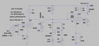
In the attached schematic, I just started with the ratio as I described earlier, then adjusted for the null, by ear and scope. It's very quiet.
About R20/C20 there must, as I see it, be something fundamentally wrong as ripple is minimized when they are removed. But ripple is low anyway.
You mean R20/C5? In my simpler version here, there are only two different common references, so I don't know if the somewhat more complex version is the issue. So let's look at the extremes of the anti-noise injection.
Assuming that the ripple with no connection is arbitrarily 1.
With the ratio of the divider, formed by the input cathode resistor, and series resistor (R20) equal to 1/input u, then the noise should be 0.
If the ratio is half of what it should be, then too much noise will be injected. At some ratio, it might be more noise than 1.
With the cap but no R20, then the full amplitude of the noise at the output cathode node, will be at the cathode of input. At this point, the input cathode is effectively bypassed too. I haven't thought this through, but I'd expect this could increase noise over the case where there is no connection between the cathodes, more than 1.
What happens in the sim if you leave out R20 but keep the cap? Maybe something about the supply too? I've included it in the attachment.
Sheldon
http://www.diyaudio.com/forums/atta...e-801-amp-801loftin-white-sn7-full-schema.gif
Last edited:
Disaster without R20. The bigger value the better, infinite best. I guess the LW theory doesn´t apply here.
Maybe better do a ripplefree(as good as possible) PSU and concentrate on to make the best of the audio circuit?
It is also important to check what happens at startup if the input tube starts conducting slower than the output or viceversa.
Maybe better do a ripplefree(as good as possible) PSU and concentrate on to make the best of the audio circuit?
It is also important to check what happens at startup if the input tube starts conducting slower than the output or viceversa.
Disaster without R20. The bigger value the better, infinite best. I guess the LW theory doesn´t apply here.
In practice with my 801 L/W amp, the noise increases on either side of the null. The null is fairly narrow. The noise phase should be opposite on either side too, but I've not checked it.
My curiosity got the better of me. The noise does indeed invert from one side of the null to the other. My old Tek 454 scope is not very sensitive. When I tested with no injected noise, I had to crank the pot a bit to see the effect. I wanted a bigger noise signal, so I connected the B+ via a 0.1u cap to one leg of the mains. With that I could see the null within 1/2 turn of the twenty turn, 20k pot. These measurements were taken at the output, referenced to common.
Sheldon
Last edited:
The 3A5 can easily answer the call!
With shunt cascode (the best sounding 300B driver I have made) you can drive 2A3 to full output with only 0,6V rms.
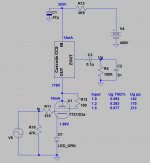
The 3A5 is very easy to use with filament bias, so I have drawn that, and drive it with my Filament Regulators (shameless, I know).
Shunt-cascode + Filament bias means NO capacitors in the signal path, except the output coupler.
Can't figure the circuit out. Does this schematic represent both havles of the 3A5 in parralell? Using LT spice gain is only about 25, no where near driving a 2A3. The other issue is selecting the operator point and then you are adding extra current from the CCS for the BJT, withou taffecting the operating point? It seems this has to be perfect as too much extra current and the shunt just quits. Most other tubes all have the same issue, each side of the BJT have nearly the same DC voltage, how do you get a set of parameters that makes the DC idle shunt side of the ccs half of the plate voltage like in this schematic so you have headroom for the shunt to swing at least 100Vpk-pk.
The only success I've had in with a 6n6p supplying the BJT ~180 V , able to swing 100V and drive the 2A3 without a 1:2 input transformer, gain is about 30. But I want a better understanding as I feel I lucked into this set of parameter. I fully understand the fixed plate voltage current mode, What I don't get is the "extra" currrent for the BJT, and setting the shunt side of the BJT DC op point. It would seem to me that the 50V you show at the shunt is half what it needs to be in order to swing the 100V needed to drive 2A3.
Lars has built some sims up, using the 3A5 model. Yes, it's both halves of the 3A5. I haven't used the LTspice 3A5 model, but the Koren ECC88 model certainly works well - please find the attached sim to demo the Shunt Cascode with ECC88. It gets 43dB even with unbypassed cathode resistor.
But the circuit does not need simulation to show its gain - or its worth!
If you have grasped the fixed anode voltage idea, you're most of the way there.
If the triode cannot change its anode voltage, the only way it can respond to changes in grid voltage is to change its anode current. where can this change in current go? Kirchoff's Law dictates that the sum of currents into and out of the anode node must be zero. Since the current-source supplying the anode won't change, the only option is for the PNP emitter to take the current swing. The PNP is happy to do this - it sees its mission in life to fix the anode voltage, as an emitter follower. And like any emitter follower, it passes variable currents at a fixed voltage. The current is passed to the output resistor, which converts current into voltage.
The output resistor is biassed at 45V. When the triode draws the greatest current, the resistor is left with the least current, or zero (voltage falls to 0V). When the triode draws the least current in the swing, the output resistor must eat the greatest current (voltage rises to 100V).
What's the gain? well, any old data sheet gives gm or S in mA/V [or milli mhos]. This is the "slope" or mutual conductance. It directly gives us the mA of current we get for every volt of input. The output resistor (in K ohms) directly converts mA to V. The gain is simply
gm x Rout..........[R in Kohms, gm in mA/V]
So the shunt cascode reduces to a triode that operates with fixed voltage. it takes voltage at the grid, and controls current output. mA for volts. But mA per V is exactly gm, which is a fundamental property of a triode. We are at last using a triode in a fundamental operating mode, uncoloured by having its anode voltage moving around at the same time as the current. No wonder it works better like this!
Attachments
I finally figured that the extra current from the CCS allows one to adjust the BJT output DC level.
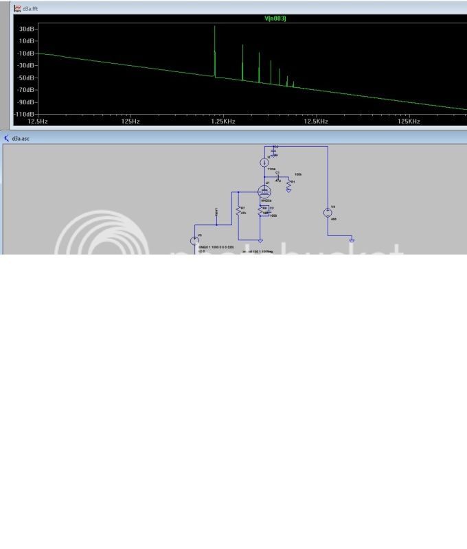
The 3A5 was about the worse tube I could find. These simulation were all done with 6S4S (similar to a 2A3) with a 3.5:40 into a 40 ohm ortho headphone load. All at 1Watt.
Without the BJT, best I could do with 6c45p, 5842, and D3a triode was around 2h -32db, and 3A5 a wopping -28db 2H. With the 6n6pi I could get -42, but the 6n6p doesn't have enough gain and would need a stepup transformer on the input. These new ortho headphone sound very good but require a lot of voltage swinng.
With the BJT mostly the same results, except the 6n6p with the BJT gave the gain I need and it lowered distortion to -52db 2H with a good harmonic spectrum. I know its just a simulation but I think it is encouraging enough to try.
Thanks Rod for sharing another inovative topology.
Last edited:
Member
Joined 2009
Paid Member
Without the BJT, best I could do with 6c45p, 5842, and D3a triode was around 2h -32db, and 3A5 a wopping -28db 2H. With the 6n6pi I could get -42, but the 6n6p doesn't have enough gain and would need a stepup transformer on the input. These new ortho headphone sound very good but require a lot of voltage swinng.
With the BJT mostly the same results, except the 6n6p with the BJT gave the gain I need and it lowered distortion to -52db 2H with a good harmonic spectrum. I know its just a simulation but I think it is encouraging enough to try.
I'm surprised at the distortion levels from the 3A5 with the BJT, I thought it was going to be more linear than this. What were the operating points - it needs to be sitting at fairly high current so that the signal swings don't bring it down to where the curves get crowded ?
I'm also surprised at the high distortion mentioned in conjunction with the D3A which I have found in practice to be quite linear - in driver duty I run them at 20mA and they can easily swing a couple of hundred Vpp with excellent linearity.. I've lost the data so I've no hard numbers, but a vague recollection of under 1% (-40dBr) at something like 200Vpp across a 100H plate choke into 50K/100pF..
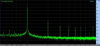
Simulation and real live.I've lost the data ..
At 200Vpp only 0.6% measured THD!
Attachments
Maybey this tube moels are poor I am using sbench modded Koren from the intact webside for the IDHT, for the 3A5 I used the dmtriode models same as Revintage.
I agree the numbers seem low, as I built a WE417 spud headamp 5k:32 that woud measure -65 2H (.7VRMS out)
I would question the revalance of the last simulation without an AC couple 2a3 stage, 3.5k:40 transformer with 8Vrms output acorss the load. and we could good do some comparisons, It would be intersting. But the distortion of the firste stage without pushing th2A3 is not telling us much.
Nothing new that D3a is a very potent and low distortion component. Nice if you build a preamp etc.
Have you guys ever heard of distortion cancellation? Distortion of the driver alone is unimportant. You must do your sims with driver+2A3/6B4G. Using bench D3a model triodestrapped gives many times(4-5) higher distortion than 3A5.
Nothing special about this! 2A3 isn´t very linear so the driver has to have the same distortion characteristics to conteract.
Last edited:
- Home
- Amplifiers
- Tubes / Valves
- does the 3A5 have the stones to drive a 2A3?