Hi Bigun, The key to the circuit behaviour is that the triode is not a voltage amplifier, but a voltage-to-current amplifier (transconductance amplifier). Grid voltage in (delta-Vg) gives current out (delta Ia).
The current is converted to voltage only by the load resistor. That's simply because the current (delta-Ia) has nowhere else to go (by design, and by Kirchoff's law). The BJT does not convert current to voltage.... you can easily demonstrate this by setting Rload = zero. Then, the voltage out is zero, but the current swing is almost entirely unchanged.
The BJT is not acting in an amplifying capacity at all - its one and only function is to fix the anode voltage to the value set by the (fixed) cascode voltage. If you prefer circuit analogies, think of it as an emitter-follower - with only a dc input. The emitter has very low output impedance, driving a very high output impedance (the triode's anode). Therefore the emitter totally defines the voltage. An emitter values holds its properties well, regardless of collector current - when correctly designed.
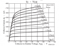
Please look again at the 2SA1319 Vce vs. Ic, for 100mA. See how it is almost perfectly flat, for the chosen operating conditions, as the output voltage rises & falls. There's only negligible amplifying effects at work there.
This is the opposite condition of a common-base voltage amplifier. In that arrangement the emitter is driven by an ultra-low impedance driver (eg transformer winding) to define the signal input voltage.
The outcome is that the amplifier's behaviour is characterised by the triodes Ia (out) versus Vg (in), for fixed anode voltage. in the usual datasheet curves, this looks like a vertical load line. Provided the resistor behaves properly, the deviation from triode behaviour is miniscule.
One further advantage is that the current in the output resistor can be set to give Vout = 0 while there is still non-zero current in the triode. Thus, we avoid running into the curly low-current region, if we design aright.
O, and did I mention that it sounds superb - good enough to make you forget about horrible recycled 1950s circuits forever.
The current is converted to voltage only by the load resistor. That's simply because the current (delta-Ia) has nowhere else to go (by design, and by Kirchoff's law). The BJT does not convert current to voltage.... you can easily demonstrate this by setting Rload = zero. Then, the voltage out is zero, but the current swing is almost entirely unchanged.
The BJT is not acting in an amplifying capacity at all - its one and only function is to fix the anode voltage to the value set by the (fixed) cascode voltage. If you prefer circuit analogies, think of it as an emitter-follower - with only a dc input. The emitter has very low output impedance, driving a very high output impedance (the triode's anode). Therefore the emitter totally defines the voltage. An emitter values holds its properties well, regardless of collector current - when correctly designed.
Please look again at the 2SA1319 Vce vs. Ic, for 100mA. See how it is almost perfectly flat, for the chosen operating conditions, as the output voltage rises & falls. There's only negligible amplifying effects at work there.
This is the opposite condition of a common-base voltage amplifier. In that arrangement the emitter is driven by an ultra-low impedance driver (eg transformer winding) to define the signal input voltage.
The outcome is that the amplifier's behaviour is characterised by the triodes Ia (out) versus Vg (in), for fixed anode voltage. in the usual datasheet curves, this looks like a vertical load line. Provided the resistor behaves properly, the deviation from triode behaviour is miniscule.
One further advantage is that the current in the output resistor can be set to give Vout = 0 while there is still non-zero current in the triode. Thus, we avoid running into the curly low-current region, if we design aright.
O, and did I mention that it sounds superb - good enough to make you forget about horrible recycled 1950s circuits forever.
Attachments
As we have pointed out the loadline is vertical. If we go to the Ua/Ia from the first post it can se that lineraity can be somewhat bettered if we go from 100 to 80V Ua. It puzzles me though that the simmed distortion is lower than the one you calculate from the loadline. Unlinearity is, I understand it, predominantely 2nd order.
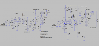
Oops, Bigun discreetly pointed out a faux pas in the post 55 schematic. This should work a little better:
This was a tester for the eyes - I cannot detect a single difference from the No 55 drawing!
As we have pointed out the loadline is vertical. If we go to the Ua/Ia from the first post it can se that lineraity can be somewhat bettered if we go from 100 to 80V Ua. It puzzles me though that the simmed distortion is lower than the one you calculate from the loadline. Unlinearity is, I understand it, predominantely 2nd order.
Lars, it should be mostly second harmonic, yes.
Odd orders should be reduced, when the idle-current is increased - to keep away from the curved low-current region. Us the highest current possible, and the lowest anode voltage possible (but keeping in mind that the output voltage cannot exceed the anode voltage).
Consistent with a suitable idle -Vg1, anyway! But we have so much gain, that small signals will suffice to drive to output to max....
Hey Sheldon, Have you considered the burnt away power in the cathode resistorst? [/IMG]
Can't get something (virtually perfect noise cancellation) for nothing (gonna cost some power).
By adding the anoderesistor I also suppose you worsen ripple figures?
[/IMG]
No, that's the beauty of the true L/W, ala Darius (prickly fellow, but had some good insights. It took me a while to get my head around it. Ask Ken about it.) The injection signal from cathode to cathode takes care of it. This works because the phase relationships line up perfectly.
If you go back and check the DC-design I did(the left one) it can be made with anything from 0 ohm resistors and up to cathode bias. If you go for normal cathode bias with 0V on the grid you have no current through the cascode load-resistor and can use any value you decide. It only takes the gyrator and a negative voltage of maybe 100V.
Take another look and you could maybe marry them to each other.
[/IMG]
Ah, but normal cathode bias requires a pretty fat electrolytic (which I have no religious objection to, but some do). And noise is handled with a very firm hand. The beauty in the L/W is it's simplicity, and use of redirection. This was Aikido before John Broskie was born. Even he didn't grok the original L/W.
I'll have to ponder the gyrator here. It needs an extra supply and I'd have to think how that syncs with the noise cancellation. I'm not that quick.
Sheldon
This was a tester for the eyes - I cannot detect a single difference from the No 55 drawing!
I didn't detect it either, until Bigun spotted it. I shorted the top 600R output cathode resistor, by leaving the connection between the shunt base resistor and the output cathode when I rearranged things.
Sheldon
More of the triode might shine through if the anode voltage was less firmly controlled by the BJT device by placing a resistor into the anode circuit (such as can be done in SS circuits - I did this in TGM5 for different reasons, which used an input cascode); it will be less linear.
As Rod says, seems like the BJT's contribution should be very linear, so whatever the triode expresses with be transmitted to the output grid. Keep in mind that the amp's output will be the combined contributions of the input and output tube. To the extent that it's 2nd harmonic, they will cancel or partly cancel each other, as they are in antiphase. So a very horizontal load line for the input tube (less 2nd) could actually mean more 2nd at the output.
Here, season to taste:
Attachments
Last edited:
Ah, but normal cathode bias requires a pretty fat electrolytic (which I have no religious objection to, but some do).
Hey Sheldon,
Read again, with the gyrator arrangement you can go from 0hm cathode resistor to normal cathode bias
. So it´s no need for big electrolytics if you don´t want to.Will anyway simulate the two, side by side, and inject ripple from the PSUs and see what happens.
Hey Sheldon,
Do you have possibility to rework your schematic just a little? It doesn´t sim correct as you have to low voltage over the BJT. It should be in the ballpark of 0,5 times 3A5s Ua if I have read Rods recomendations right. This means you should have something like 45V on the 2A3 grid.
You also have local feedback from the undecoupled 3A5s cathode resistor. Is that intentional?
Last edited:
Member
Joined 2009
Paid Member
Rod - yes, I see what you mean exactly. The BJT does not show it's nature at the voltage on it's collector, it is purely a signal that is developed across the collector resistor by the current modulated by the triode. The character of the BJT must appear somewhere since there has to be a voltage differential between it's base and emitter for current to flow and this is an exponential relationship. And I see now that it appears as a voltage signal at the anode of the triode - albeit a small signal and for all intents and purposes the load line will look vertical.
The load-line doesn't have to be vertical, as I already pointed out, an anode resistor in the right spot will allow the slope of the load-line to be pre-set. That's not a recommended change by the way, just an option that a designer may elect or not.
With a vertical load-line this isn't going to sound like any triode normally sounds like. The space charge in the tube will not experience any voltage fluctuation on the anode. To me, it becomes more like a pentode. It's a 'pentode wired triode'. And I ain't saying that this is a bad thing at all, but the usual factors that people weigh-up when choosing a driver/input tube likely need to change for a circuit like this. Maybe it's a case that any old toss will do for an input tube because it's going to behave quite linearly provided it's biassed up properly and can drive enough current. It doesn't even have to be a tube.
I've read over the Darius stuff carefully and it all checks out nicely - it's essentially an ultrapath connection for the cathodes of both input and output tubes. One thing I did find was that there are a couple of threads where an 'original' L-W circuit is shown with a pentode driver - the voltages and resistor values are clearly screwed up if you check them carefully.
Last edited:
Do you have possibility to rework your schematic just a little? It doesn´t sim correct as you have to low voltage over the BJT. It should be in the ballpark of 0,5 times 3A5s Ua if I have read Rods recomendations right. This means you should have something like 45V on the 2A3 grid.
You also have local feedback from the undecoupled 3A5s cathode resistor. Is that intentional?
Ahh yes, I think I see what you mean. Something like this one attached: I put the pot in there for fun. Could vary the gain, could also combine this with the variable load line, but I didn't want to clutter it up too much. Can leave it out it too and just connect the CCS directly to the plate and increase the current to 8.5mA.
Yes the unbypassed input cathode resistor needs to be there for the noise compensation. Options here too, if we want to explore that. And there is
Darius's "triode factor" too.
Sheldon
Attachments
Last edited:
Sorry, couldn't help myself (the pot is my weak attempt to show a dual wiper version - good luck finding that in real life, fixed resistors would be the call anyway, but clutters up the schematic):
Variable load line tap, variable shunt voltage/gain tap. Of course gain can also be varied with adjustment of shunt resistor and shunt current. Lots of ways to dial in this shunt thingy (I'm beginning to sound like a low rent version of Ken).
Sheldon
Variable load line tap, variable shunt voltage/gain tap. Of course gain can also be varied with adjustment of shunt resistor and shunt current. Lots of ways to dial in this shunt thingy (I'm beginning to sound like a low rent version of Ken).
Sheldon
Attachments
Sorry for being so slow witted, revintage, but I'm gradually getting the hang of this (I think). Took a second look at my last two ideas and realized that the numbers didn't work (I was sorta backwards on the output bias voltage). This version is closer. One potentially nice feature of tapping the input anode (not shown on this version), is that it can allow some more headroom by setting the input voltage to the shunt higher. It cost a little in terms of gain, but we can get that back in the shunt resistor. We then need more voltage for the shunt base, but can then just use a divider from B+ instead of tapping the output cathode.
Your thoughts on this one:
Your thoughts on this one:
Attachments
Last edited:
Member
Joined 2009
Paid Member
I likes it a lot. Can we use a choke anode load instead of the CCS ?
I guess you could, but you'd have to have a bypassed dropping resistor to bring down the voltage.
The CCS is a more perfect choke here, since you have plenty of B+. If you want the horizontal load line then no need for the plate resistor unless you want more room for the shunt input voltage (More on that below).
Now if you want a more typical load line, you could do something like the one below. The load line is 30k (parallel sections). You reduce the shunt amplification by 25%. but there's plenty anyway, or you could make it up by increasing the shunt resistor. As Rod says, better shunt bias supplies are easy and easy to make adjustable. With that and an adjustabe CCS, it should be fairly easy to line everything up. This one has 90V on the 3a5 plate, 6mA quiescent current. Also the shunt input voltage is increased to give some headroom for the shunt device.
Attachments
Last edited:
Bigun,
You can´t use a choke load(or gyrator) instead of the CCS as you then get that fixed voltage working against the fixed voltage at the BJT base.
Sheldon,
I see you are slowly working your way towards my solution. Instead of gyrator+neg supply you burn power by increasing B+ and 2A3 cathode resistor. I don´t understand the purpose of the 15k//4u, could you explain? Wouldn´t it be better with a cap from the BJT base to ground? But maybe this is hidden the LW-version you refer to. Also there is still local FB at the 3A5, intentional? Will come back with some simulations, side by side with Rod´s original
You can´t use a choke load(or gyrator) instead of the CCS as you then get that fixed voltage working against the fixed voltage at the BJT base.
Sheldon,
I see you are slowly working your way towards my solution
. Instead of gyrator+neg supply you burn power by increasing B+ and 2A3 cathode resistor. I don´t understand the purpose of the 15k//4u, could you explain? Wouldn´t it be better with a cap from the BJT base to ground? But maybe this is hidden the LW-version you refer to. Also there is still local FB at the 3A5, intentional? Will come back with some simulations, side by side with Rod´s original
Last edited:
With a vertical load-line this isn't going to sound like any triode normally sounds like. The space charge in the tube will not experience any voltage fluctuation on the anode. To me, it becomes more like a pentode. It's a 'pentode wired triode'. And I ain't saying that this is a bad thing at all, but the usual factors that people weigh-up when choosing a driver/input tube likely need to change for a circuit like this. Maybe it's a case that any old toss will do for an input tube because it's going to behave quite linearly provided it's biassed up properly and can drive enough current. It doesn't even have to be a tube.
Hi Bigun, The Shunt Cascode's vertical load line is not like the normal resistor loaded triode, it is true. However, this is not a loss - it's an advantage!
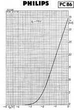
The snapshot of the PC86 data tells the tale. Here, the triode is characterised for anode voltage fixed at 175V. Please try taking a ruler to the graph: dead straight from 7mA to 35mA+ !
Now build a stage. If we run PC86 at 12mA, just like the data sheet, and use a load resistor of 20K. Set the CCS to 16mA, to get idle conditions of 4mA and 80V in the load resistor.
The PC86 gives 14mA/V, so an input swing of about +/- 0,25V will give an output of +/-4mA and +/- 80V. And, this whole excursion will be performed in the dead-straight linear section of the triode.
Many other triodes behave exactly the same way. Better still, triodes & triode-connected pentodes that don't sound too good with a varying anode voltage really come to life with shunt cascode. PCC89 in RIAA stage is an example of superb potential from ultra-cheap TV valve.
Listening results are immediate and vivid.
By comparison, please try assessing the linearity of a 6SN7 or any other favourite triode, using a resistor load. The outcome varies for different triodes and operating points, resulting in the need to experiment and tube-roll - rather than design.
Some DIYers aim for a sound that recreates the 1950s, and I will leave them to do that, without comment.
But for open-loop gain stages aimed at the most natural sound, we need more linearity.
Attachments
Have done quite a few test with different working-points and -loads. 3rd harmonic seems to change very little but 2nd harmonic varies. I have an idea of letting 2nd harmonic dominate as it might mask the higher h´s somewhat. Silly or????
I have done a few sims with the folded hybridcascode loaded by a DC-connected Schaded tetrode(no loadresistor) and a gyrator. Seems to work OK in theory.
About EC86 this is a very nice tube for other audio-applications, too. Must try! Have a model if anyone else likes to play.
I have done a few sims with the folded hybridcascode loaded by a DC-connected Schaded tetrode(no loadresistor) and a gyrator. Seems to work OK in theory.
About EC86 this is a very nice tube for other audio-applications, too. Must try! Have a model if anyone else likes to play.
Sheldon,I see you are slowly working your way towards my solution
That bias supply I have is a poor afterthought, and assumes that the average current to the base of the shunt resistor is a constant. Shoulda just left an undefined voltage source to avoid confusing the important points. I've used the following bias supply from Morgan Jones (ignore the output voltage, just an example). It's probably overkill, and could be done with fewer sections. Also easy to make adjustable. The common reference for the supply is not too important, as the final adjustment of noise cancellation takes care of it anyway.
Yes, the local feedback is required to inject the noise from the output cathode in antiphase to the imput. And it avoids a cap there. But one could divide the input cathode resistor and partially bypass it, to reduce the local FB and still provide some unbypassed resistance to generate antiphase noise at the input cathode.
Attachments
Last edited:
Hey Sheldon,
Have done the sims and they show a little more than double the ripple in yours compared to mine. Shorted input and 5V/100Hz added in the PSU.
No big difference if changing the 50k value. You will have to fill me in if I missed something.
BUT...... when grounding C6 as I proposed the ripple got a little lower than mine.
With feedback removed it indicated the higher harmonics where higher.
Attachments
- Home
- Amplifiers
- Tubes / Valves
- does the 3A5 have the stones to drive a 2A3?