What kind of gain could you get out of a 26 using this arrangement? Usually around 9 - could this be screwed up to 40 or 50? Would that be a suitable driver?
Andy
Hi Andy, with the 26 in filament bias (unbypassed 10R), the effective gm is almost unchanged at about 1,1mA/V.
If 26 idles at 6mA at 156V, you could run it over a current excursion of say, 4-8mA. This would allow 2mA in the output resistor. If the 2A3 grid is to swing +/- 78V, then the output resistor should be 39K.
Gain is gm x Rout = 1,1 x 39: about 43.
Alternatively, look at the 4П1Л (4P1L).
For 600mA filament bias and datasheet grid voltage of -7,0V: the cathode resistor is about 12R, and effective gm about 5,6mA/V.
With Ia = 60mA, you could have say, 10mA in the output for 0 to 150V swing, This sets the output resistor at 7,5K, and the gain = 5,6 x 7,5: about 42.
Compare with my 300B driver: EF184 in triode: (S=15mA/V) output resistor 27K; gain >300. With this, gainless (or no) preamp is realised, even for low output (100mV pk) sources.
Note also that the shunt cascode operates with a static anode voltage, therefore Mr Miller is not crushing you with his habitual burden. The input capacitance is just the Cgf + Cga of the triode, without upscaling from the gain. The is the killer for CCS-loaded high-gain triode stages - and demands very low impedance preamp drive.
Lars, if the bias battery is 100V and the idle current is the output is 3,5mA into 15K, then the idle grid voltage is -100 + 52,5V or about -47V (biassing the 2A3 correctly). The excursion can then be from around 0V to -100V with the 3A5 in clean class-A: enough to fully drive the 2A3. The usual rule to have 2x headroom in a driver is not necessary with shunt cascode, because the Driver valve can be kept well away from Ia=0.
In practice, the ability to reference the output to ground improves the sound more than the advantage of getting rid of the FT-2 coupling cap - and this has been my choice in my own amplifier. EMI rejection is of the highest importance!
In practice, the ability to reference the output to ground improves the sound more than the advantage of getting rid of the FT-2 coupling cap - and this has been my choice in my own amplifier. EMI rejection is of the highest importance!
Member
Joined 2009
Paid Member
The second one will probably be impossible to realize due to start-up making the powertube grid go positive. Fun to play with anyway.
I get an error message 'couldn't find symbol(s) TRIODEH'
Member
Joined 2009
Paid Member
oh, I was being slow, I didn't recognize what Q1 was doing. It reminds me that I had proposed something like this before (see Q6 in the schematic at post 5): http://www.diyaudio.com/forums/solid-state/194268-dx-hybrid-amplifier-will-produced-soon.html
It makes for a nice hybrid, but I'm not sure that strictly, the 3A5 is driving the 2A3 unaided. The I-V curve of Q1 matters.
It makes for a nice hybrid, but I'm not sure that strictly, the 3A5 is driving the 2A3 unaided. The I-V curve of Q1 matters.
Last edited:
") .
.It makes for a nice hybrid, but I'm not sure that strictly, the 3A5 is driving the 2A3 unaided. The I-V curve of Q1 matters.
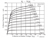
Achieving stable characteristic of Ic vs Vce will be addressed in competent design-work. The benefit of optimum choice of transistor, and the operating point can be illustrated by the 2SA1319 characteristics - see attached. With this 160V-durable PNP, the Early Effect [variation of Ic with Vce] is negligible for 100mA and below, and 10V Vce or more. These limits are easily sufficient to allow a shunt-cascode to perform.
The quality of the cascode voltage-source is critically important & the use of shunt regulation is not overdoing it.
sure, it takes some work to get these designs realised optimally, but when you have heard the performance of this single-stage driver, there is no going back to muddy old 2-stage drivers, with 6SN7s or other such tired-out recycled circuitry.
Attachments
Member
Joined 2009
Paid Member
PM me with your E-mail address and I will send the *.asy.
PM sent.
...sure, it takes some work to get these designs realised optimally, but when you have heard the performance of this single-stage driver, there is no going back to muddy old 2-stage drivers, with 6SN7s or other such tired-out recycled circuitry.
I've read enough to avoid a 2-stage driver design although I have not built one myself (life is short).
Still, I would prefer to keep the BJT curves out of the signal path in the case that I'm trying to achieve a DHT - DHT combination such that the performance of the amplifier is determined by these DHTs - adding in the I-V curve of a BJT must change the outcome. I'm not sure that this is what I want, given that I can simply use a 6C45Pi as a driver without any sand ?
Bigun,
Another option is planer tubes, whether they qualify for your definition of DHT is another question. I've used Russian planers 6S17K-V (http://www.etd.su/pdf/113/6/6S17KV.pdf) and GS-4B, prefer the latter. They are highly non-microphonic which is another plus. I just solder wires directly to the tube that I use as leads, and they are cheap. I've no experience with them driving a 2A3, but I have driving a GU-15 a directly heated pentode I'm runing trioded.
Matt
Still, I would prefer to keep the BJT curves out of the signal path in the case that I'm trying to achieve a DHT - DHT combination such that the performance of the amplifier is determined by these DHTs - adding in the I-V curve of a BJT must change the outcome. I'm not sure that this is what I want, given that I can simply use a 6C45Pi as a driver without any sand ?
This is the not-so-subtle difference with a cascode transistor: there are no curves. It's a flat current-in, current out transfer, whole orders of magnitude less curvy than any common-emitter transistor (or even triode) amplifier transfer characteristic. See the bottom line of the graph in the previous post. Competent design is a prerequisite, though.
The 6C45 will work, but then you have to deal with the excessive input capacitance (described above). If you have a very low output impedance preamp, no problem, otherwise it's almost another stage required. Opamp outputs, or 12AX7s - not good enough!
The difference between 6C45 curves and the 3A5/4P1L's (for instance) are not small, so this is no DHT-DHT amplifier, either. And, you also have to cope with the stability weaknesses of the 6C45.
But tradeoffs make a design, and its your money, and your ears.
PM sent.
I've read enough to avoid a 2-stage driver design although I have not built one myself (life is short).
Still, I would prefer to keep the BJT curves out of the signal path in the case that I'm trying to achieve a DHT - DHT combination such that the performance of the amplifier is determined by these DHTs - adding in the I-V curve of a BJT must change the outcome. I'm not sure that this is what I want, given that I can simply use a 6C45Pi as a driver without any sand ?
I think the 3A5/bi-polar cascode has merit, worth trying IMO. (You can always replace it later if you don't like it.) In this case the transistor provides no current gain at all, but it does provide a lot of additional transconductance which is where the additional gain is realized. (Perhaps not quite the right way to put it)
Member
Joined 2009
Paid Member
Well the idea is growing on me again (it seems a long whiles since the DX hybrid thread).
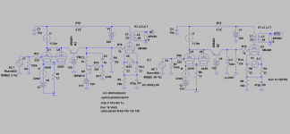
On a slightly different topic - a Loftin-white version from Broskie (attached) The Tube Cad Journal: Design Idea-A safe Loftin-White amplifier - I wonder if the 3A5 might be a candidate for this too.
If I'm to get out the soldering iron I will need to order some parts, I have the 6B4G but not the 3A5. I have plenty of sand.
It's a common base amplifier, it's very much in the signal path. But any concerns are academic until I've heard it. If the day job will allow some time I may give this a try.
On a slightly different topic - a Loftin-white version from Broskie (attached) The Tube Cad Journal: Design Idea-A safe Loftin-White amplifier - I wonder if the 3A5 might be a candidate for this too.
If I'm to get out the soldering iron I will need to order some parts, I have the 6B4G but not the 3A5. I have plenty of sand.
In this case the transistor provides no current gain at all, but it does provide a lot of additional transconductance which is where the additional gain is realized.
It's a common base amplifier, it's very much in the signal path. But any concerns are academic until I've heard it. If the day job will allow some time I may give this a try.
Attachments
Last edited:
Hi Rod and Bigun!
We would have to look at the Hfe as a funktion of collector current, as the base current adds to (subtracts from) the collector current, and any variation in base current will be reflected at the output to the tube.
Anyway, I think it is a nice schematic Rod, and I might try it.
Thorsten
We would have to look at the Hfe as a funktion of collector current, as the base current adds to (subtracts from) the collector current, and any variation in base current will be reflected at the output to the tube.
Anyway, I think it is a nice schematic Rod, and I might try it.
Thorsten
Last edited:
Hi Rod and Bigun!
We would have to look at the Hfe as a funktion of collector current, as the base current adds to (subtracts from) the collector current, and any variation in base current will be reflected at the output to the tube.
Anyway, I think it is a nice schematic Rod, and I might try it.
Thorsten
hi Thorsten,
With a carefully chosen transistor, and operating conditions, the base current robs a minor linear fraction from the output current. A FET would fix that, naturally, but the FET's gm is too low, and capacitance too high (in most circuits).
Compare this flaw with other means of getting the same gain. With 2 triode stages, you multiply the nonlinearities of the first stage in the second stage. These nonlinearities include the variation of gm across the large-signal swing (this alone is worse than the base current error). The power-supply rejection (lack of it!) is also amplified by stage 2.
I use a shunt-cascode with a JFET for MC cartridge stage, shunt-cascode RIAA (the eq stage works really well), shunt cascode PA driver. Shunt-cascode from MC to 300B - only 3 stages needed, and I have gain to spare!! The sound of it is superb.
Attachments
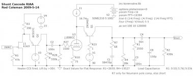
The 3A5 can easily answer the call!
With shunt cascode (the best sounding 300B driver I have made) you can drive 2A3 to full output with only 0,6V rms.
The 3A5 is very easy to use with filament bias, so I have drawn that, and drive it with my Filament Regulators (shameless, I know).
Shunt-cascode + Filament bias means NO capacitors in the signal path, except the output coupler.
Thanks for posting this circuit. Please explain the function of the MPSA92; I\m sorry to say I do not see the reason for its inclusion in the design. I have in the past built various stages using active loads and of course constant current sinks, but have never (knowingly) had any solid state devices in the signal path, which in this case there appears to be.
Thanks in advance
The circuit operation:
The PNP MPSA92 is fed with constant voltage at the base. This forces the triode's anode voltage to be constant, too - 0,6V higher than MPSA92's base.
The triode is biased to give idle current - say 5mA. The whole stage is fed from a CCS - say 10mA fixed. So 5mA flows into the triode, the rest has only the PNP as a way out [remember Kirchoff's law]. So you have 5mA in the triode, & 5mA in the PNP, which flows into the load resistor - where the current is turned into a voltage.
Now apply some grid voltage. The anode voltage is fixed by the PNP, so only the anode *current* can change. But the overall supply current is also fixed, so only the output current can move.
Thus, the triode becomes a current-pump (a transconductance amplifier, for jargon fans). The fixed anode voltage frees it from the compromises forced by the (internal) anode resistance - so that the gain can be set by the output resistor, without having to consider the B+ value, or the value of anode-current.
The gain becomes gm x Rout. It easily exceeds the triodes mu, which is the limit for CCS loaded stages. And it has no Miller effect, unlike CCS loaded stages.
Since the Music current only circulates between the triode and the load, the supply current is constant instantaneously (not just on average, like a normal SE class A stage). This means that the power supply capacitor carries no Music signal - a huge advantage in itself. And the gain is so high, that the triode's cathode resistor can be unbypassed - eliminating another perennial nasty. Lars has shown that it can also run into the following stage with dc-coupling (lose the coupling capacitor, too), so you can have a capacitor-free driver stage!
I might mention that it sounds better than any other architecture I have tried.
Disadvantages? Needs a PCB for proper layout really, but it can be made small & low priced - and the other parts are quite ordinary. I am laying one out now.
Also, for very high gain stages, attention to stability criteria is important, but again, the PCB controls this well.
- Home
- Amplifiers
- Tubes / Valves
- does the 3A5 have the stones to drive a 2A3?