Member
Joined 2009
Paid Member
Same results here, I guess I don't consider the shunt 3A5 a good direction, thats a lot of added distortion.
I figure that there are two issues to bear in mind. Firstly, linearity isn't necessarily better with a near-vertical load-line compared with a near-horizontal load-line. Secondly, there is a voltage variation at the plate when using a BJT cascode, as I pointed out earlier. The base-emitter junction has to vary in order for the current through the transistor to vary. This voltage variation is related to the signal through the exponential transfer function of the transistor and appears at the plate, modulating the tube current in equivalence as applied to the control grid reduced by a factor of mu.
Well, a horizontal load-line isn't necessarily more linear either. In fact it presents difficulties that are far more difficult to design around.
For practical circuits, a constant-current load gives high gain (which you enjoy), but high gain is directly at the anode, which gives correspondingly high miller capacitance at the grid. Even for small triodes with Cak of 2-4pF, you can wind up seeing 100pF or more at the input (ie less than 80K ohm at 20kHz), and the previous stage won't like it.
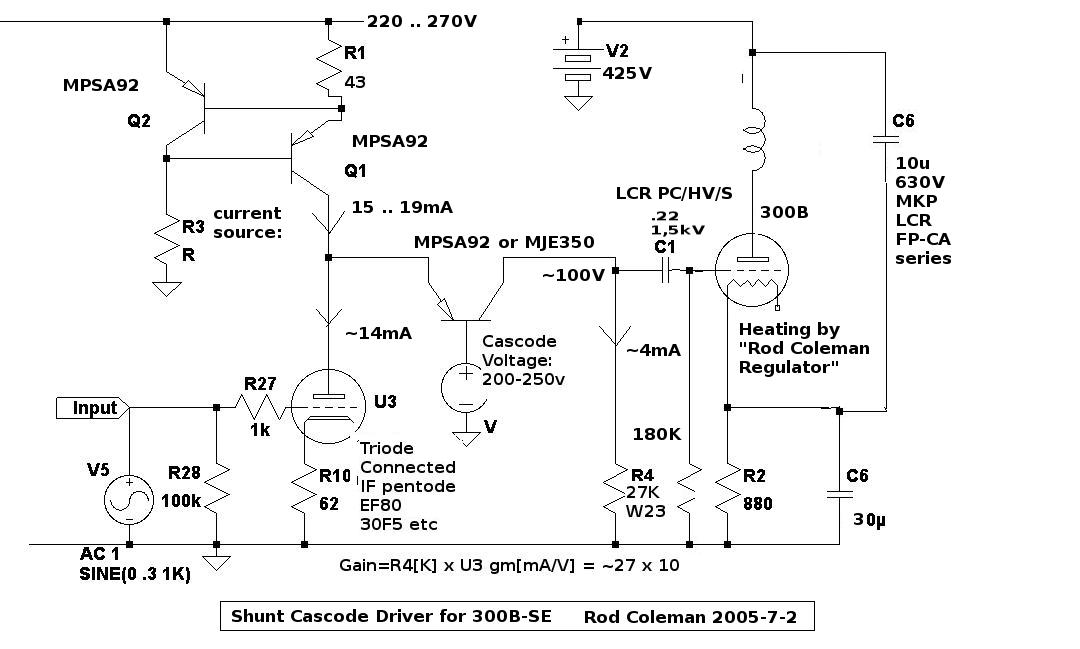
As for effect of Vbe on the shunt cascode, let us consider a MPSA92 transistor in a 150V shunt-cascode with a PC86 triode -
A 30K load resistor yields a gain of about 300 (dependent on the bias method). The output idles at 75V, and can peak at 150V for a anode-current swing of 2.5mA.
This current-swing is passed wholly by the MPSA92 - so what is the delta in Vbe?
Modelling the circuit in LTspice with the 2N5401 shows that it is about 10mV. So on a 150V anode voltage you are imposing a change of less than 70 parts per million.
The anode resistance (slope) is about 5K for PC86, so a 10mV change yields an anode-current delta of 2uA.
In other words, at 100% +ve output swing there is below -60dB shortfall in the expected peak current.
The corresponding case for a horizontal load-line would require an anode CCS experiencing a 75V swing, while maintaining current stable to within 2uA. Stable to 2uA across all wanted frequencies, too - meaning low capacitance is required. This equates to 37.5Mohms, and below 1pF of leakage capacitance.
A cascoded depletion FET would give comparable, or slightly better than this target.
But, the CCS loaded amplifier would only have a gain of about 65 - meaning you would need to swing about 4x as grid voltage to get the same voltage output. In almost every case, this would take the voltage into the high-voltage region of the triode, where the curves begin to compress, and the low-voltage region, where they expand. This distortion would be many times worse than the -60dB effects we are witnessing from Vbe changes.
Add to that the serious problems of input-loading caused by the high Miller capacitance, and it becomes clear that the horizontal load-line stage has major distortion effects to contend with, that are almost completely avoided in shunt-cascode.
.
For practical circuits, a constant-current load gives high gain (which you enjoy), but high gain is directly at the anode, which gives correspondingly high miller capacitance at the grid. Even for small triodes with Cak of 2-4pF, you can wind up seeing 100pF or more at the input (ie less than 80K ohm at 20kHz), and the previous stage won't like it.
As for effect of Vbe on the shunt cascode, let us consider a MPSA92 transistor in a 150V shunt-cascode with a PC86 triode -
A 30K load resistor yields a gain of about 300 (dependent on the bias method). The output idles at 75V, and can peak at 150V for a anode-current swing of 2.5mA.
This current-swing is passed wholly by the MPSA92 - so what is the delta in Vbe?
Modelling the circuit in LTspice with the 2N5401 shows that it is about 10mV. So on a 150V anode voltage you are imposing a change of less than 70 parts per million.
The anode resistance (slope) is about 5K for PC86, so a 10mV change yields an anode-current delta of 2uA.
In other words, at 100% +ve output swing there is below -60dB shortfall in the expected peak current.
The corresponding case for a horizontal load-line would require an anode CCS experiencing a 75V swing, while maintaining current stable to within 2uA. Stable to 2uA across all wanted frequencies, too - meaning low capacitance is required. This equates to 37.5Mohms, and below 1pF of leakage capacitance.
A cascoded depletion FET would give comparable, or slightly better than this target.
But, the CCS loaded amplifier would only have a gain of about 65 - meaning you would need to swing about 4x as grid voltage to get the same voltage output. In almost every case, this would take the voltage into the high-voltage region of the triode, where the curves begin to compress, and the low-voltage region, where they expand. This distortion would be many times worse than the -60dB effects we are witnessing from Vbe changes.
Add to that the serious problems of input-loading caused by the high Miller capacitance, and it becomes clear that the horizontal load-line stage has major distortion effects to contend with, that are almost completely avoided in shunt-cascode.
.
Last edited:
BJT capacitance modulation
Hello everybody!
First, let me say this is very interesting thread, especially the neat cascode circuit and its thorough analysis presented by Rod Coleman. BTW, I would call it 'hybrid folded cascode' according to accepted name cobnventions for such circuits, but author has the right to choose a name of course!")
I am also in the camp of mixed SS-tube solutions. But what worries me in the
common base BJT stage is the capacitance modulation with voltage, which was not addressed here. One can really neglect Early effect and Vbe variation by competent design, but it is more difficult to get rid of collector-base capacitance Ccb variation with voltage according to ~1/sqrt(Vcb). In realistic high-voltage BJT this capacitance has the value ~<10pF, and its variation with 100V voltage swing could easily reach 2-3pF. At frequencies ~ 10kHz such capacitance has impedance around 10 MOhm. So we have in parallel with Rload=15kOhm some parallel impedance, varying with voltage with relative peak-to-peak amplitude 15k/10M=0.0015 or 0.15%.
That serves as estimation of the peak harmonics current. The value is not that large, but we have to take into account the spectrum of such distortion: Fourier transform of 1/sqrt(x) is ~1/f^2 IIRC. So this spectrum is slowly decreasing with frequency and can cause some nasties in the sonics department. Since simplest simulator models did not take into account Ccb variation, the most reliable way to measure such effects is to measure distortions in real sircuit at low and high frequencies. Does somebody did it already?
Hello everybody!
First, let me say this is very interesting thread, especially the neat cascode circuit and its thorough analysis presented by Rod Coleman. BTW, I would call it 'hybrid folded cascode' according to accepted name cobnventions for such circuits, but author has the right to choose a name of course!
I am also in the camp of mixed SS-tube solutions. But what worries me in the
common base BJT stage is the capacitance modulation with voltage, which was not addressed here. One can really neglect Early effect and Vbe variation by competent design, but it is more difficult to get rid of collector-base capacitance Ccb variation with voltage according to ~1/sqrt(Vcb). In realistic high-voltage BJT this capacitance has the value ~<10pF, and its variation with 100V voltage swing could easily reach 2-3pF. At frequencies ~ 10kHz such capacitance has impedance around 10 MOhm. So we have in parallel with Rload=15kOhm some parallel impedance, varying with voltage with relative peak-to-peak amplitude 15k/10M=0.0015 or 0.15%.
That serves as estimation of the peak harmonics current. The value is not that large, but we have to take into account the spectrum of such distortion: Fourier transform of 1/sqrt(x) is ~1/f^2 IIRC. So this spectrum is slowly decreasing with frequency and can cause some nasties in the sonics department. Since simplest simulator models did not take into account Ccb variation, the most reliable way to measure such effects is to measure distortions in real sircuit at low and high frequencies. Does somebody did it already?
Hello! I am pleased to hear of your interest in the circuit.
It is called 'Shunt Cascode' to show the major difference in operation compared to the usual series-cascode that is used everywhere.
It is true that some Ccb modulation will occur.
Example: in most circuits the very cheap MPSA92 transistor (300V durability) works very well in this circuit. For 300B driver, with V+ = 190V and output swing of +/-70V the transistor voltage swings from about 20V to 160V (driver triode Va=170V fixed).
The corresponding swing in capacitance is about 1,8pF to 3,5pF using ON typical data. Similar performance can be had from 2SA1480, which also allows high power handling (up to 7W).
Keep in mind that the load will also show capacitance, usually much higher than this 3,5pF - maybe 100pF for a end-stage DHT, or even more for a cable. This will cause ultrasonic rolloff, determined by the load resistor value.
We must keep in mind that, even with a 15K load resistor, we get a gain of 150 to 250. Compared to other architectures - even with CCS loads - you normally need two stages to reach such a gain. In this case, the distortions of one stage will be multiplied by the next, leading to far more serious effects.
Still, I agree that it is worth measuring the circuit, to complete the characterisation. I am not far from doing that, now that I have just bought a wideband spectrum analyser, we will see!
I will attempt this after perfecting the demonstration circuit - with twin shunt-regulators on V+ and Vcascode.
But I can say for sure that the sonic nasties are far lower using shunt-cascode than the usual 2-stage 6SN7 circuit used to drive 300Bs - which suffer badly from confusion and lack of articulation & immediacy.
But I can say for sure that the sonic nasties are far lower using shunt-cascode than the usual 2-stage 6SN7 circuit used to drive 300Bs - which suffer badly from confusion and lack of articulation & immediacy.
I think quite a few driver stages are better than the "usual 2-stage 6SN7 circuit" or its variations with different tubes, bypassed cathode resistors etc. That got left behind a couple of years ago. Personally, I have no design skills in solid state and I'm very happy with two stages of 4P1L in filament bias with interstages. No coupling caps or bypassed cathode resistors. But I look forward to this and other clever hybrid solutions that are emerging as driver stages for the venerable 300b. This is all very good stuff!
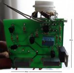
Here's a practical implementation.
This 50mm x 50mm board does not hole the shunt regulation, but it will in the next spin.
Shunt regulation seems well worth the trouble for a few extra parts.
A self-stabilising function, to allow dc-coupled fixed-bias in the output stage is also possible for this architecture.
This 50mm x 50mm board does not hole the shunt regulation, but it will in the next spin.
Shunt regulation seems well worth the trouble for a few extra parts.
A self-stabilising function, to allow dc-coupled fixed-bias in the output stage is also possible for this architecture.
Attachments
Ccb modulation
We'll wait for results...
Good luck!
Yes, but hopefully this additional capacitance can be taken as constant (within some approximation, of course) but for our purpose we can put it constant. So it will draw some additional current at the same frequency, which does not change much in the estimation of peak harmonics current ratio to total current.Keep in mind that the load will also show capacitance, usually much higher than this 3,5pF - maybe 100pF for a end-stage DHT, or even more for a cable. This will cause ultrasonic rolloff, determined by the load resistor value.
I fully agree with this reasoning, that is why I said I definitely like the circuitWe must keep in mind that, even with a 15K load resistor, we get a gain of 150 to 250. Compared to other architectures - even with CCS loads - you normally need two stages to reach such a gain. In this case, the distortions of one stage will be multiplied by the next, leading to far more serious effects.
Still, I agree that it is worth measuring the circuit, to complete the characterisation. I am not far from doing that, now that I have just bought a wideband spectrum analyser, we will see!
I will attempt this after perfecting the demonstration circuit - with twin shunt-regulators on V+ and Vcascode.
We'll wait for results...
This is not a surprise (at least for me), because 'usual 2-stage 6SN7 circuit' can hardly serve as good benchmark due to several reasons (not necessary to repeat them here). Another question - what we can choose as a reference circuit to compare with? There is no universal answer (many people have their own preference), but for the purpose of this experiment (I mean to compare HF distortion behaviour), perhaps the 'standard' serial cascode with 2 tubes will fit the goal. ONLY THIS GOAL, not as universal reference circuit, due to evident disadvantages of the serial cascode already mentioned by you. In such a comparison we can (at least in principle) to compare the HF spectra of optimized BJT common-base stage with vacuume triode (or pentode) common grid stage, both driven from DHT. May be this difference will shed a light on the difference in SS and tube sound.But I can say for sure that the sonic nasties are far lower using shunt-cascode than the usual 2-stage 6SN7 circuit used to drive 300Bs - which suffer badly from confusion and lack of articulation & immediacy.
Good luck!
Thanks!
I am pleased to hear that other DIYers do not like the 2-stage 6SN7 driver. But there are too many makers still trying to squeeze good sound from this bad circuit - a classic case of polishing a jobbie.
The shunt cascode is nearest in performance to a pentode driver. You get the same low-capacitance input, which is a useful comparison.
The pentode needs a much cleaner power supply, and in every way is worse-sounding, but it is nearer than a 6SN7 or similar circuit. In fact, anyone with a 6SN7 driver can see what they are missing by driving a DHT with the 6П15П or the 6BW7 (pentode mode, 12mA, VG2= 150V RC-divider).
Maybe pentode is best reference? At least the input capacitance means that the signal source is not affected - which would be the case if we compare with a high-gm triode single-stage.
pentode instead of cascode
But it is even closer to 'natural' serial cascodeThe shunt cascode is nearest in performance to a pentode driver.
This family (EL83 etc.) of second-generation video output pentodes is one of the best suited pentodes to the task IMHO. But I would exclude 6П15П from the list - it is not so successful clone of EL83 (it was derived partially from the clone of EL84 with some mods to get parameters close to that of EL83). EL83 sounds much cleaner.In fact, anyone with a 6SN7 driver can see what they are missing by driving a DHT with the 6П15П or the 6BW7.
Pentode is definitely closer than a high-gm triode single-stage. But the spectrum of pentodes usually differs significantly from that of triodes. Moreover, if we want to make an unambiguous comparison it is better to change only one parameter at a time. From this point of view the standard cascode is the best reference, since we can keep the same input triode and change only upper triode to PNP BJT.Maybe pentode is best reference? At least the input capacitance means that the signal source is not affected - which would be the case if we compare with a high-gm triode single-stage.
There are some variations in 6П15П construction though?
Many pentodes to choose from. Some of them - IF pentodes - have the same pin-assignment through the range (EF80 family). These types can also be triode connected and used in Shunt-Cascode, when the gm is 7mA/V or more.
Yes, we can also compare series-cascode using NPN transistor in the top position. This arrangement sounds better than a triode in the top-position, even when agricultural NPN is used (BU408 etc). Again, we can triode-connect EF80,6BW7 etc, and compare using same valve.
Yes, there are some minor variations. Long-life Hi-Rel versions also exist: 6П15П-ЕВ, 6П15П-ЕР. But all of them (at least NOS soviet tubes) have boxed plates (similar to EL84) instead of oval plates with gap like EL83.There are some variations in 6П15П construction though?
Again you mention one of my preferrable tube familyMany pentodes to choose from. Some of them - IF pentodes - have the same pin-assignment through the range (EF80 family). These types can also be triode connected and used in Shunt-Cascode, when the gm is 7mA/V or more.
Not only my indeed.But for 300B they have not enough guts IMHO, for 2A3 - may be, never tried.
This is a real surprise for me!! If such sonics superiority will be confirmed by measurements - I would rank it as major discovery in audio circuitry!!!Yes, we can also compare series-cascode using NPN transistor in the top position. This arrangement sounds better than a triode in the top-position, even when agricultural NPN is used (BU408 etc).
This is what we are waiting for!Again, we can triode-connect EF80,6BW7 etc, and compare using same valve.
Member
Joined 2009
Paid Member
But it is even closer to 'natural' serial cascode
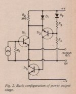
There's always lots of names for more or less the same topology - I've usually referred to this one as a "Taylor" after the design published in p301, Wireless World 1973 by P. L. Taylor at the University of Salford (UK).
His amplifier was all-transistor but Broskie has also published it as a hybrid tube-BJT on his blog.
Taylor Source Follower
Attachments
Taylor-Broskie follower
Broskie's hybrid implementation of Taylor's follower is more complicated circuit (as well as Taylor's original), since it has: a) feedback, b) push-pull operation. I believe that solid-state folded cascode appeared long before Taylor's publication, but I could not find a proper reference now.
Both Taylor's and Broskie's circuits contain too long feedback loop (serving as phase inverter in addition) IMHO, that could lead to phase matching problem at HF.
Going back to Rod's circuits - they are non-FB. And the most intriguing (for me) statement, that even in usual serial cascode configuration DHT+NPN BJT can sound better than DHT+triode on top. If we take for comparison high-gm (>10mA/V) triode for top position, I do not see a physical reasons for that. But it does not mean that it's impossible! That is why audio is such an interesting hobby...
Member
Joined 2009
Paid Member
By cascoding the triode we shift the load line to more or less vertical (I like to think of it as 'pentode wiring a triode' but that's just me) - and some tubes maybe better suited to this than others. Does anyone have suggestions about which input tubes might make the best candidates for this approach (even if not the 3A5 that prompted this thread) ?
Broskie's hybrid implementation of Taylor's follower is more complicated circuit (as well as Taylor's original), since it has: a) feedback, b) push-pull operation. I believe that solid-state folded cascode appeared long before Taylor's publication, but I could not find a proper reference now.
Both Taylor's and Broskie's circuits contain too long feedback loop (serving as phase inverter in addition) IMHO, that could lead to phase matching problem at HF.
Going back to Rod's circuits - they are non-FB. And the most intriguing (for me) statement, that even in usual serial cascode configuration DHT+NPN BJT can sound better than DHT+triode on top. If we take for comparison high-gm (>10mA/V) triode for top position, I do not see a physical reasons for that. But it does not mean that it's impossible! That is why audio is such an interesting hobby...
Yes, the circuit is not related to the Taylor in any way, and works quite differently.
Series-Cascode works better with NPN, not a triode in the top position because the gm of NPN is so high.
In any cascode, series or shunt, the stability of the cascode voltage is the essential question, and must be as good as you can make it. A shunt-regulator is always a good idea.
Series-Cascode with triode 10mA/V and Ia=10mA, Swing (delta-Ia)=5mA, the voltage stability is > 500mV.
For NPN transistor in same circuit, the NPN has gm > 200 throughout the swing; the voltage stability will be better than 16mV.
I believe that this explains the improvement in sound I heard when I compared a PC86 to a BU406 NPN cascoding a triode-connected EF80 (as 300B driver). I did not record any spectrum at the time of the test, sadly.
The NPN was fed from a darlington, to give good base-current drive. A shunt regulator will do this job properly.
But the circuit gave me the idea to develop shunt-Cascode. This circuit is much better than series cascode: the input AND output are referred to ground, so the power-supply rejection is much improved. You can have very high gain, even with triodes that run with Va=100V. Also, when you have small grid voltages, you can use variable-mu triodes like ECC89. The high gain keep the signal away from the curved characteristic. RIAA with Shunt-Cascode ECC89 sounds excellent!
Gareth, any triode with anode current of 2 to 20mA, and gm of 8mA/V or higher, will give excellent results in Shunt Cascode. From current production, a JJ E88CC can be a good choice.
But one of the great advantages of the circuit is that you can use almost any TV triode or pentode (triode connected) and get good results. Small tubes with high gm are just made for this circuit, and they have little or no microphony, and can often replace 2 stages with one stage.
But one of the great advantages of the circuit is that you can use almost any TV triode or pentode (triode connected) and get good results. Small tubes with high gm are just made for this circuit, and they have little or no microphony, and can often replace 2 stages with one stage.
tubes for cascode
Another combination is E55L trioded as input valve with 6С19П (aka 6S19P) as top tube. The beauty of this circuit is in grid connection of the top tube to ground directly. Bias voltage of 6S19P is high enough to serve as anode voltage for E55L trioded. This cascode provides large voltage swing and good current capability. According to auhtor (Sergey Vasyanin) Gain=90, Ri=2.2kOhm, distortions at Vout=110V RMS with transformer load: 2nd harmonic -45dB, 3rd -75dB, 4th -85dB, all others - below -100dB. At lower signals the picture is even better.
From what I've read on forums, russian 6Н30П (aka 6N30P) is good in cascode (both halves are used).Does anyone have suggestions about which input tubes might make the best candidates for this approach (even if not the 3A5 that prompted this thread) ?
Another combination is E55L trioded as input valve with 6С19П (aka 6S19P) as top tube. The beauty of this circuit is in grid connection of the top tube to ground directly. Bias voltage of 6S19P is high enough to serve as anode voltage for E55L trioded. This cascode provides large voltage swing and good current capability. According to auhtor (Sergey Vasyanin) Gain=90, Ri=2.2kOhm, distortions at Vout=110V RMS with transformer load: 2nd harmonic -45dB, 3rd -75dB, 4th -85dB, all others - below -100dB. At lower signals the picture is even better.
Last edited:
I got your reasoning. I assumed that 500mV swing on the plate of the input valve is negligble value. From the load-line point of view, going form gm=200 to 10, we go from almost vertical load-line to little bit inclined one. It seems it is of no consequence. But may be it does matter... If this is the main reason, one can use highest gm tube on top. There are several 50mA/V small signal tubes available. Perhaps famous D3a is up to the task.Series-Cascode with triode 10mA/V and Ia=10mA, Swing (delta-Ia)=5mA, the voltage stability is > 500mV.
For NPN transistor in same circuit, the NPN has gm > 200 throughout the swing; the voltage stability will be better than 16mV.
I believe that this explains the improvement in sound I heard
- Home
- Amplifiers
- Tubes / Valves
- does the 3A5 have the stones to drive a 2A3?