I got your reasoning. I assumed that 500mV swing on the plate of the input valve is negligble value. From the load-line point of view, going form gm=200 to 10, we go from almost vertical load-line to little bit inclined one. It seems it is of no consequence. But may be it does matter... If this is the main reason, one can use highest gm tube on top. There are several 50mA/V small signal tubes available. Perhaps famous D3a is up to the task.
Maybe I would have taken some more time with the Series-Cascode (Triode versus NPN) - but this circuit, (2005 year) gave me the idea for Shunt Cascode, and I stopped work.
But the BU408 (TV horizontal sweep NPN) certainly sounded better than triode PC86 (14mA/V) for 300B driver.
With Shunt Cascode, the stability of the base voltage (=cascode voltage) also has a big effect on the sound. Please use regulation, preferably shunt regulation!
I'm trying to make sense of this. Granted, this is only simulation and the tube is 4P1L, but will repeat the sims with the 3A5.
Attachments
simulation
Ikonflexer,
the difference in current source schematics between two circuits can be responsible for the difference in harmonic spectra. Try to use the same current source in both cases. One can take MOSFET version and for Shunt Cascode circuit just disconnect the left end of R8 from divider R6-R7 and connect it to the plate of U1. (So R8 will be in parallel with C1, C2). This will fix DC levels.
Hm, ok, I will give it a try. V4 is DC in simulation (well, AC with 0 amplitude, same thing).
LTspice spectra are taken from ac tests, which use the small-signal fields of the voltage-source model. The small-signal voltage should be explicitly zero, or preferably a dc model used - any swing on this source will have a dramatic effect.
Hey guys,
You forget current cancellation in 2-stage power-amps where the shunt cascode seems to shine. Do the sims together with a reliable model of 2A3 or 300B to get realistic sims. Think I mentioned this in the beginning of this thread where I showed that parallelled halves of 3A5 will work.
The simmed shunt cascode results as singlegain stages(actually they are twostage DC-coupled) aren´t that impressing for me either. Have tried quite a few high-gm triodes. As straight Ug/Ia-line as possible should be needed.
Last edited:
Hey guys,
You forget current cancellation in 2-stage power-amps where the shunt cascode seems to shine. Do the sims together with a reliable model of 2A3 or 300B to get realistic sims. Think I mentioned this in the beginning of this thread where I showed that parallelled halves of 3A5 will work.
The simmed shunt cascode results as singlegain stages(actually they are twostage DC-coupled) aren´t that impressing for me either. Have tried quite a few high-gm triodes. As straight Ug/Ia-line as possible should be needed.
Indeed, the final result with a 2A3 or 300B is better.
The 3A5 can easily answer the call!
With shunt cascode (the best sounding 300B driver I have made) you can drive 2A3 to full output with only 0,6V rms.
The 3A5 is very easy to use with filament bias, so I have drawn that, and drive it with my Filament Regulators (shameless, I know).
Shunt-cascode + Filament bias means NO capacitors in the signal path, except the output coupler.
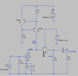
Rod, what is the trick to select right operating points for both 3a5 and MPSA92? I tried lots of combination, and got the following in the sims. Everything looks amazingly good, 0.63V input at 3a5 which 2A3 output 2.1W w/1% THD.
Now if you could please tell me how to make a good stabilized voltage source for MPSA92, then it will be super prefect!
")
Attachments
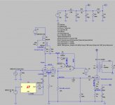
Rod, what is the trick to select right operating points for both 3a5 and MPSA92? I tried lots of combination, and got the following in the sims. Everything looks amazingly good, 0.63V input at 3a5 which 2A3 output 2.1W w/1% THD.
Now if you could please tell me how to make a good stabilized voltage source for MPSA92, then it will be super prefect!
Choose about 20% to 40% of the value of anode idle current in the output resistor.
The higher the ratio, the more stable it will be, but the gain will drop.
You can divide the 150V with resistors (and cap!), and buffer with another MPSA92 follower, to produce the cascode voltage. but for best results, a shunt regulator can be used.
BTW, I produced PCBs for the shunt cascode, including driver heater regulation, and shunt regulation for the incoming voltage, and the cascode voltage. I just haven't had time to characterise them, and support them yet. too much industrial work!
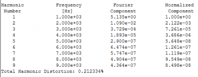
3A5 12R cathode resistor with 2.76 Vk would require 227mA cathode current.
Something looks wrong with that sim.
Rk should be 336.6R for the indicated 8.2mA anode current.
The circuit makes use of a fixed bias method, which called filament bias. 3A5's filament current is provided by the LT1085 current source. Current provided= (1.25V/5.6ohm) = app. 223mA, at the same time this current generates 2.76V over the unbypassed 12R cathode resistor. And this bias voltage will in turn draw 8.2mA anode current.
Choose about 20% to 40% of the value of anode idle current in the output resistor.
The higher the ratio, the more stable it will be, but the gain will drop.
You can divide the 150V with resistors (and cap!), and buffer with another MPSA92 follower, to produce the cascode voltage. but for best results, a shunt regulator can be used.
BTW, I produced PCBs for the shunt cascode, including driver heater regulation, and shunt regulation for the incoming voltage, and the cascode voltage. I just haven't had time to characterise them, and support them yet. too much industrial work!
Got it Rod, thanks for that. I will use your suggestion and see how much more gain I can squeeze from the 3a5.
Really looking forward for your PCBs/kits/pre-built etc, do count me in
Last night I was thinking what if I can make a small board, consisting of Anode CCS+Shunt Cascode+Regulated V source with a VR105 gas tube? That must be terrific for both outlook and performance!
With only 3A5, VR105, 2A3 on top of the chasis, it really is a cool looking amp!!!
The circuit makes use of a fixed bias method, which called filament bias. 3A5's filament current is provided by the LT1085 current source. Current provided= (1.25V/5.6ohm) = app. 223mA, at the same time (the filament current + anode current) generates 2.76V over the unbypassed 12R cathode resistor. And this bias voltage will eventually draw 8.2mA anode current.
Correction
Checking back in with this project, I ordered Filament Regulators from Rod last December, and still haven't gathered all the parts for this (!) but really want to get it going. Rod, it sure sounds like you have your plate full; is there any chance of at least getting some finalized PCB layouts / schematics so we can start experimenting? Hope that's not an offensive question to ask, but if it is I wholeheartedly apologize in advance!
Checking back in with this project, I ordered Filament Regulators from Rod last December, and still haven't gathered all the parts for this (!) but really want to get it going. Rod, it sure sounds like you have your plate full; is there any chance of at least getting some finalized PCB layouts / schematics so we can start experimenting? Hope that's not an offensive question to ask, but if it is I wholeheartedly apologize in advance!
Thank you! No problem in asking.
The boards have been here a little while, and I have to develop them a little more, to make it the kind of design that just plugs in and works. Shunt Cascode has many advantages, including very high gain - but this gain can provoke instability, if the proper suppression components are missing.
I am looking at them intermittently now, and hope to have a reliable design ready soon!
- Home
- Amplifiers
- Tubes / Valves
- does the 3A5 have the stones to drive a 2A3?