Hi Anatoliy,
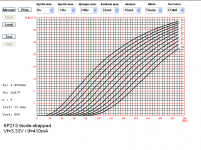
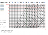
Traced some curves on both 4P1L and 12P17L to compare both triode strapped performance. See attached.
12P17L is really linear albeit it has greater gm than the 4P1L. Valve book says gm=6 for 4P1L and gm=8 for 12P17L.
I thought you may find the 12P17L plot useful.
Also plotted the 4P1L with filaments running at 500mA which is how I used them on my Siberian Preamp. You can see that curves are flatter than when filament current is 660mA (both filaments in parallel).
Cheers,
Ale
For the 4p1l, odd that the mu was 9 at 500ma and only 6 at 660ma ?
For the 4p1l, odd that the mu was 9 at 500ma and only 6 at 660ma ?
True, I don't trust those fixed measures done by the app. You can't change the measurement point. Mu shouldn't change though, despite running the tube at a lower filament current? I will re-run the tests when possible
True, I don't trust those fixed measures done by the app. You can't change the measurement point. Mu shouldn't change though, despite running the tube at a lower filament current? I will re-run the tests when possible
I thought maybe I was missing something, cause the spec heat is giving a mu much lower than previous tests I've seen. I would think lower heat would lower transductance, maybe it would increase mu. But the mu=6 at the spec 660ma , thats my main concern. I'm really strecthing the gain for this DHT pre/headphone out I'm slowly putting together.
Really appreciate all you data and discovery of this tube. I always dismissed it as a "paralleled" tube, usually parallel means more distortion. Like 2a3, or even dual idht's.
I have 4 of these russians still wrapped up ready to go when I get there. Something special about tubes this old that have truly never been used. Thats one thing I think may be why the measurements you have gotten are so good.
Hi Regal,
I plotted both curves again and got same results. Not happy with the results, did a simple test with a CCS.
*
Tested 4P1L with 1Vrms input signal and quiescent current point of 20mA (Vgk=-5.15V).
*
Results:
If=500mA, Ia=2011mA,Va=94V, Vo=9.44Vrms, THD=0.04%, u=9.44
If=650mA, Ia=20.1mA, Va=79V, Vo=9.41Vrms, THD=0.08%, u=9.41
*
As expected distortion is halved whilst anode quiescent point is higher for 500mA filament current. Mu remains the same...
*
Hi Regal,
I plotted both curves again and got same results. Not happy with the results, did a simple test with a CCS.
*
Tested 4P1L with 1Vrms input signal and quiescent current point of 20mA (Vgk=-5.15V).
*
Results:
If=500mA, Ia=2011mA,Va=94V, Vo=9.44Vrms, THD=0.04%, u=9.44
If=650mA, Ia=20.1mA, Va=79V, Vo=9.41Vrms, THD=0.08%, u=9.41
*
As expected distortion is halved whilst anode quiescent point is higher for 500mA filament current. Mu remains the same...
*
So at 500ma we gain mu and lower distortion, but on your plots the Rp stayed the same. If thats right then 500mA should best way to go all around.
Forget the plots. Gimp clearly demonstrated that the curve tracing board wasn't accurate for high gm valves unless you tweak a couple of sensing resistor, which I haven't done. Also you can't control in the software which is the measurement point for mu, gm and rp. So I don't trust the results.
I did a manual test to demonstrate that u remains nearly constant.
The reason why I run the filaments at 500mA is because given previous advice (see previous posts) I found this filament current point the optimal in terms of microphonic noise and distortion. The 4P1L is massively linear, however by reducing the filament current to 500mA when both filaments are connected in parallel, I found it performs the best.
I have the 4P1L socket suspended with paracord. perfect solution for this nice valve.
Thank you Ale; looks interesting. Not exactly the same tube of course, but 12P17L looks like a good compromise if it is less microphonic.
Anatoliy,
Surprised with my first test results. Measured a simple 12P17L stage with a CCS load.
I played around to find the best operating point at Ia=15mA (or higher current) and biased at Vgk=-12.5V (LED array). Va=178V
Stage gain is about 10.5.
Interesting to find was that THD wasn't as good as a 4P1L. Got minimum of 0.17% (other DHTs perform far better than this)
I may need to do further testing to find a better sweet spot for this tube...
Attachments
Went back to revisit my 6P21S tests. The 6P21S is a very nice power directly heated tetrode on an octal base. The heater is designed to run on 6.3V supply, not cheap at all, but a great candidate.
I believe I found a sweet spot in terms of distortion for this tube. I reduced the filament current to 400mA and got the following results:
Lowest distortion at:
Ia=15mA / Va=129V and Vgk=-4.9V (LED array bias)
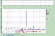
THD=0.008% when loaded with a 47K resistor. Really linear. See attached frequency response diagram.
This is not a high microphonic tube, so should rewire my preamp to what this big fellow to perform again!
Edit: interesting to see how the third harmonic rises a bit over the second when running the tube at this low filament current. Keen to listen to the change in tone (if I can notice the difference though!)
I believe I found a sweet spot in terms of distortion for this tube. I reduced the filament current to 400mA and got the following results:
Lowest distortion at:
Ia=15mA / Va=129V and Vgk=-4.9V (LED array bias)
THD=0.008% when loaded with a 47K resistor. Really linear. See attached frequency response diagram.
This is not a high microphonic tube, so should rewire my preamp to what this big fellow to perform again!
Edit: interesting to see how the third harmonic rises a bit over the second when running the tube at this low filament current. Keen to listen to the change in tone (if I can notice the difference though!)
Attachments
Yeah, not a fountain. Apparently her place at the output.Surprised with my first test results.
http://audioportal.su/attachment.php?attachmentid=71661&d=1316170997
Sorry for the links , pictures place does not work.
Last edited:
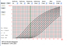
Some more tests on the 6P21S. The third harmonic components is explained when you plot the anode curves for that filament current. See attached.
Proper triode curves appear when If=450mA.
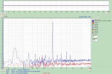
Went back and did further tests with If=450mA and distortion is around 0.10%. When lowered down to If=410mA got a superb 0.04% which is the best I can get out of a 26/226 stage at the moment.
Remember back when I tried the sound of the 6P21s stage and was really nice.
Will trace curves again with If=410mA to see the difference...
Proper triode curves appear when If=450mA.
Went back and did further tests with If=450mA and distortion is around 0.10%. When lowered down to If=410mA got a superb 0.04% which is the best I can get out of a 26/226 stage at the moment.
Remember back when I tried the sound of the 6P21s stage and was really nice.
Will trace curves again with If=410mA to see the difference...
Attachments
Ale, are all your tests using the same input voltage (sine wave)? IMHO it would be interesting to compare the distortion at the same output voltage. Let's say what you want is to get 5V p-p output. Given that 4P1L has a different mu than type 26, they will require different input voltages to achieve the 5V p-p. The difference in distortion might be even more pronounced.
Ale, are all your tests using the same input voltage (sine wave)? IMHO it would be interesting to compare the distortion at the same output voltage. Let's say what you want is to get 5V p-p output. Given that 4P1L has a different mu than type 26, they will require different input voltages to achieve the 5V p-p. The difference in distortion might be even more pronounced.
Yes all tests are based on 1Vrms sine input at 1kHz and you are right about that!
")
Some more tests on the 6P21S. The third harmonic components is explained when you plot the anode curves for that filament current. See attached.
Proper triode curves appear when If=450mA.
Went back and did further tests with If=450mA and distortion is around 0.10%. When lowered down to If=410mA got a superb 0.04% which is the best I can get out of a 26/226 stage at the moment.
Remember back when I tried the sound of the 6P21s stage and was really nice.
Will trace curves again with If=410mA to see the difference...
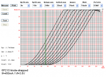
Now traced curves with filament at 410mA. See attached. They are really linear within the quiescent point tested before
I may try this configuration in my Siberian instead of the 4P1Ls....
Attachments
My planes are to use the 4P1L with ikoflex's output stage. Cheaper than an OPT and can have a direct headphone output.
As far as microphonics it may be an problem without an OPT, but I think its worth a shot, see any issues?
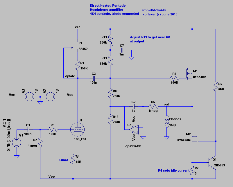
Very interesting design. I was looking at trying out this very simple circuit based on Broskie's hybrid CF+:
http://www.diyaudio.com/forums/tubes-valves/202283-dht-headphone-hybrid-cf.html
I will run the 4P1L at 20mA, lower filament current as stated below in my previous posts and suspend the sockets. Specially if you are planning to use them in a headphone amplifer. Why not changing the current FET CCS with a gyrator Mosfet?
I need to study the circuit to understand how the servo operates with the output mosfets
Honestly don't have much experience with the gyrator design.
I have a LTspice simulation of the buffer portion of Iko's schematic I can send you, I can't find a flaw in it. I did some intensive Gootee analysis of the servo and it stays well out of the midrange in the simulations.
- Home
- Amplifiers
- Tubes / Valves
- 4P1L DHT Line Stage