Well, Thats all pretty interesting!
I really should get my scope out and do some tests too. It would be interesting to see where the onset of distortion is actually happening above 8W, whether in the driver or the O/P stage...
--Have to open the FB loop to do that though, and alter I/P level accordingly...
To sharpen up the square-waves, it may be worth dropping the value of the PI grid-coupling resistor to 100K, (or just link it out) in view of what a previous poster mentioned concerning the Miller capacitance of that stage....
Worth trying anyway, see if it makes a difference...
Hi Alastair , in previous post I talked about input capacitance only , because the phase spliter didn't make any amplification , its a unity gain and therefore it haven't any Miller capacitances .Well, Thats all pretty interesting!
I really should get my scope out and do some tests too. It would be interesting to see where the onset of distortion is actually happening above 8W, whether in the driver or the O/P stage...
--Have to open the FB loop to do that though, and alter I/P level accordingly...
To sharpen up the square-waves, it may be worth dropping the value of the PI grid-coupling resistor to 100K, (or just link it out) in view of what a previous poster mentioned concerning the Miller capacitance of that stage....
Worth trying anyway, see if it makes a difference...
Well, Thats all pretty interesting!
I really should get my scope out and do some tests too. It would be interesting to see where the onset of distortion is actually happening above 8W, whether in the driver or the O/P stage...
--Have to open the FB loop to do that though, and alter I/P level accordingly...
To sharpen up the square-waves, it may be worth dropping the value of the PI grid-coupling resistor to 100K, (or just link it out) in view of what a previous poster mentioned concerning the Miller capacitance of that stage....
Worth trying anyway, see if it makes a difference...
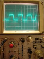
Yep drop the scope on the pl519..see what the O/P is...
")
It's quite interesting this is the first test I have done on this amp...i've just been listening to it...
Regards
M. Gregg
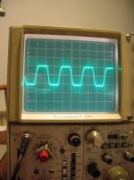
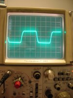
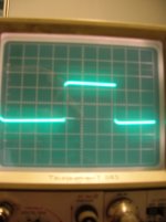
Yes of course , because this resistance reducing the high frequency response of the amp , and this is visible in the 10 Khz square wave . The shape of the square 10Khz and 20khz tell as a lot about the frequency response , it must looking as good as a square .Dimitris AR,
Just asking because of your previous post...
Looking at the square wave do you think the 470K on the phase splitter/driver is responsible for the slight slope?
Or coupling capacitor issue?
Regards
M. Gregg
Yes of course , because this resistance reducing the high frequency response of the amp , and this is visible in the 10 Khz square wave . The shape of the square 10Khz and 20khz tell as a lot about the frequency response , it must looking as good as a square .
I will try using a direct connection...and see what happens.
I think you suggested 10K..I have seen some other schematics with a direct "no resistance connection"..what value do you use in your amps?
Regards
M. Gregg
Hi guys... I am curious why you didn't just build the Tim Mellow amp in the first place although I certainly understand the satisfaction of the design it your self aspect... I am assembling the parts to build a Tim Mellow amp and could make it so that I could convert to your input-driver scheme and power supply. I am not sure what you are trying to achieve here so if you could please fill me in I would appreciate it and then I can decide to make my chassis a convertable or to just go your route or the Tim Mellow route. One thing I do like about the Tim Mellow is that except for the input it is direct coupled... and that does have it's advangates.
Last edited:
Wouldnt be difficult to work it out...
Assuming the capacitance is 7pF, plus capacitance of leads/sockets rest of the connections to grid, call it say, 12 pf....
Capacitive reactance of 12 pf in series with whatever resistor you fancy driving G1, will give you the attenuation at whatever frequency you decide....
--If you see what I mean....
But your 10K wouldnt cause much attenuation at say 20kHz...
Hi guys... I am curious why you didn't just build the Tim Mellow amp in the first place although I certainly understand the satisfaction of the design it your self aspect... I am assembling the parts to build a Tim Mellow amp and could make it so that I could convert to your input-driver scheme and power supply. I am not sure what you are trying to achieve here so if you could please fill me in I would appreciate it and then I can decide to make my chassis a convertable or to just go your route or the Tim Mellow route. One thing I do like about the Tim Mellow is that except for the input it is direct coupled... and that does have it's advangates.
Personally, I think the Tim-Mellow amp is flawed in a few (Many) aspects of its design.
--For instance, it relies Too Much IMO on Global-feedback to account for the difference in Drive requirements from Top to Bottom O/P tube.
--The Global-feedback also Varies with the position of the vol-pot wiper!
--But That is just My opinion--No Offence to Tim or anyone else!
My design goals were a relatively silple OTL, with NO constant twiddling-Bias Adjustments (As there Are none!) or complicated PSU's....
Last edited:
Hi guys... I am curious why you didn't just build the Tim Mellow amp in the first place although I certainly understand the satisfaction of the Design it your self aspect... I am assembling the parts to build a Tim Mellow amp and could make it so that I could convert to your input-driver scheme and power supply. I am not sure what you are trying to achieve here so if you could please fill me in I wold appreciate it and then I can decide to make my chassis a convertable or to just go your route or the Tim Mellow route. One thing I do like about the Tim Mellow is that except for the input it is direct soupled... and that does have it's advangates.
This is only my opinion....
The Tim Mellow design has a few issues..For one there is an offset issue with the center point of the power supply +/- rails...a few people have found this linked to the 1K in the center point..
There seems to be a problem liked to the feedback post 110# this thread..
Alastair is the best person to expand this for you..
The other issue is some people have had some of the idle settings seem to drift and heat up one tube switch off and all goes back to normal then it happens again..
One other issue is do you know how much heat the 4 6c33cs will generate..running both heaters and power drawn from the mains..
With the auto bias you can switch in the heaters and run at lower power if you want...
Many people seem to like the Tim Mellow design..so I guess you will too.
Each to his own I guess..
Regards
M. Gregg
Wouldnt be difficult to work it out...
Assuming the capacitance is 7pF, plus capacitance of leads/sockets rest of the connections to grid, call it say, 12 pf....
Capacitive reactance of 12 pf in series with whatever resistor you fancy driving G1, will give you the attenuation at whatever frequency you decide....
--If you see what I mean....
But your 10K wouldnt cause much attenuation at say 20kHz...
I see what you mean...only thing is we are using an "educated guess" of the capacitance for the calc..
Ok I'll try 10K LMAO...
The problem is I can't win the lottery so I guess any guess would be wrong,,,,,,
Regards
M. Gregg
Last edited:
The Capacitance of the G1 of 6SN7 is--7pf according to data sheet. The additional is a guess, but wouldnt be far out IMO...
--Close enough for 'Audio' work anyway!
Can I get a data sheet for the lottery numbers? thats not far out...LOL
I'll go with 10K...and see what happens..
Regards
M. Gregg
- Status
- This old topic is closed. If you want to reopen this topic, contact a moderator using the "Report Post" button.
- Home
- Amplifiers
- Tubes / Valves
- Vacuum Tube OTL power amp!!