You know it is kind of frustrating to try to help with suggestions and questions, but you ignore most of it. Good luck, I'm out.
Thomas
Thomas
Thomas please don't get angry, if tomorrow it does not work well I will follow your advice, but please let me try my own way first.
 ....that's a lot of help.....


Hi !
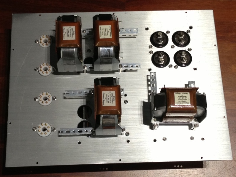
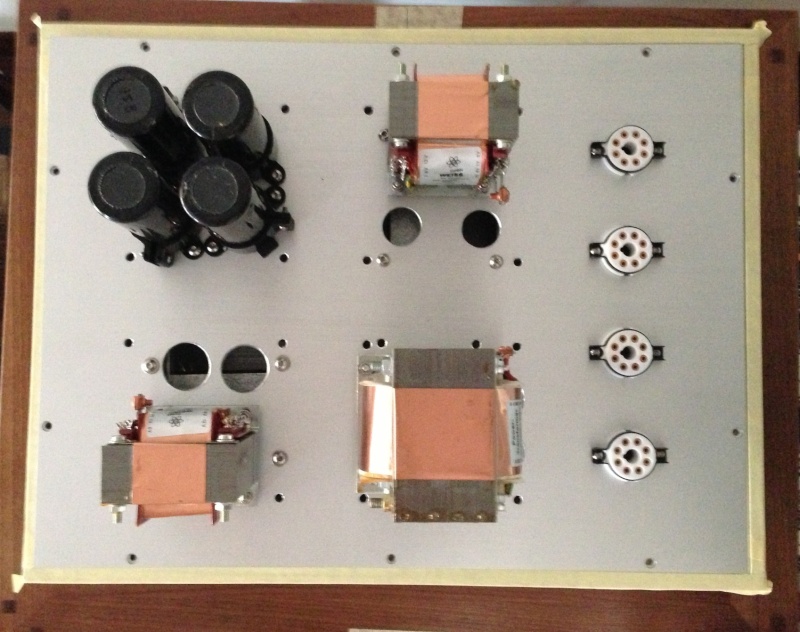
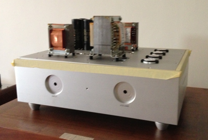
I'm making my 26 preamp. Some photo of the PSU.
Very nice.
Hi !
I'm making my 26 preamp. Some photo of the PSU.
Thats some serious noodles!
I think I see 2 anode chokes, two filament chokes, one main B+ tranny, two other trannys, for filaments? Four octals. Damper diodes?
And you have volume pot and channel selector on the PSU?
/Staffan
Thats some serious noodles!
I think I see 2 anode chokes, two filament chokes, one main B+ tranny, two other trannys, for filaments? Four octals. Damper diodes?
And you have volume pot and channel selector on the PSU?
/Staffan
Planing to use LCLCLC filter for B+ filtering. Yes. 4 octal for TV damper. 2 separate filament transformer with LCL filtering. All passive filtering used.
The place of volume pot and channel selector will house vintage Weston meters.
🙂
2 separate filament transformer with LCL filtering. All passive filtering used.
🙂
Neat. What is the L values in filament chokes?
Neat. What is the L values in filament chokes?
0.7 Hy / 1A as shown in the photo.
🙂

I have to take off the 100K grid leak resistor if I want to use 50K ladder attenuator or have I to left?
with 100k in place as // 50k the total will be 33k .... not a problem if the source can drive it,btw not low ....
Taking some time to address the grounding in my #26 preamp as there is some noise, and I got some interesting results with the frequency response.
There is a large peak at about 70KHz. If possible it would be great to get some insight on what might be causeing the instability. Has anyone else seen similar results...?
Setup is very simple - filament bias, LL1660 output
Thanks
There is a large peak at about 70KHz. If possible it would be great to get some insight on what might be causeing the instability. Has anyone else seen similar results...?
Setup is very simple - filament bias, LL1660 output
Thanks
Attachments

- Home
- Amplifiers
- Tubes / Valves
- #26 pre amp