Hi Jakob2,
I was referring to properly run tests.
Hi Chris,
I understand, but as seen in the mentioned Lipshitz/Vanderkooy/Tiefenbrunn example most test done were´t really properly executed. But were still used as examples that show/proof.......
They work, but it takes a lot of time to run a series. This would be the main draw back.
Of course, perfect listening tests do not exist; usual considerations lead to compromises and some design decisions are just subjective (see for example the desired level of significance or range of confidence interval).
It depends on the hypothesis under test.For a truly blind test, the audience isn't even told what they will be listening to.
So, I don't have a problem with those tests, properly executed of course! When you start pointing out places where a test can fall short. Any test, not properly executed is invalid, so there isn't any point in discussing those situations.
Again it depends, as perfection doesn´t exist there is most likely everytime something debateble not to mention the sometimes arbitrarly choosen boundary conditions.
So, usually it needs carefully analysis of the test documentation to decide if it was a sound experiment wrt the hypothesis and conclusions.
Unfortunately really sound experiments wrt to the effects we are discussing in the threads around here, are quite rare.
Current probe alternatives
I just came across this from Pete Millett:
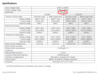
PM-TE Current Measurement Interface
$300 on eBay. Specs and the info on the link. Does this look suitable for such measurements?
I just came across this from Pete Millett:
PM-TE Current Measurement Interface
$300 on eBay. Specs and the info on the link. Does this look suitable for such measurements?
I'd be wary of the 0.4 MHz bandwidth. I've seen transformer secondary circuits ring at 1.5 MHz. Remember that John Curl's technician Rick Miller uses an AM radio to sniff out diode induced transformer ringing; the AM band extends from 0.54 MHz to 1.6 MHz. And if you follow Morgan Jones' advice to use a snubber with one R and one C you'll get ringing at even higher frequencies.
[M. Jones wants the ringing frequency to be as far away from the audio band as possible. The higher the ringing frequency, the better. That way if you screw up your snubber design, such that some amount of ringing remains, regular ordinary supply filtering will (probably) get rid of it.]
[M. Jones wants the ringing frequency to be as far away from the audio band as possible. The higher the ringing frequency, the better. That way if you screw up your snubber design, such that some amount of ringing remains, regular ordinary supply filtering will (probably) get rid of it.]
I just came across this from Pete Millett:
PM-TE Current Measurement Interface
$300 on eBay. Specs and the info on the link. Does this look suitable for such measurements?
For that money (a trifle more) I'd get this:
CMicrotek - Products
Jan
Jan the CMicrotek datasheet lists a bandwidth of 550 kHz. Higher than the Pete Millet device but, in my opinion, not high enough to observe transformer ringing. In addition to that, it's far far easier to view the ringing *voltage* since the magnitude of the ringing voltage is 10% to 30% of the peak-to-peak secondary voltage. The magnitude of the ringing part of the *current* waveform, is less than 1% of the peak-to-peak secondary current. You lose about 4 bits of resolution if you decide to measure ringing current instead of ringing voltage.
PH104, I'm not yet accustomed to the JinHan scope. I'm clumsy with it and I take a frustratingly long time to configure its settings. Also I'm acclimated to a much bigger screen with lots more pixels so this scope feels kind of cheezy.
_
PH104, I'm not yet accustomed to the JinHan scope. I'm clumsy with it and I take a frustratingly long time to configure its settings. Also I'm acclimated to a much bigger screen with lots more pixels so this scope feels kind of cheezy.
_
Attachments
Mark,
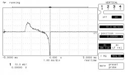
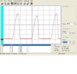
In my look at power supplies (still continuing) it seemed that most diodes conduct for about 30% of the available time. This is due to the transformer voltage rising as the current drain drops.
I do like your scope shot that seems to clearly show it is diode turn off that is the issue. Most folks seem to talk about turn on.
Also of note is shown that line noise mostly passes when the diode is conducting, and that the transformer used for the current timing has a center tap that really ain't.
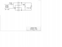
Also note as I think the current probe I made was show here way back. I bought a bunch of ferrite transformer cores and built a bunch of probes and pick the one that best shows the frequency range of interest. For low frequencies I just run a extra lead through an open frame audio transformer.
ES
In my look at power supplies (still continuing) it seemed that most diodes conduct for about 30% of the available time. This is due to the transformer voltage rising as the current drain drops.
I do like your scope shot that seems to clearly show it is diode turn off that is the issue. Most folks seem to talk about turn on.
Also of note is shown that line noise mostly passes when the diode is conducting, and that the transformer used for the current timing has a center tap that really ain't.
Also note as I think the current probe I made was show here way back. I bought a bunch of ferrite transformer cores and built a bunch of probes and pick the one that best shows the frequency range of interest. For low frequencies I just run a extra lead through an open frame audio transformer.
ES
Attachments
Last edited:
Another reason may be the flat-top waveform the utility company delivers to your/my house. It ain't exactly a sine wave.In my look at power supplies (still continuing) it seemed that most diodes conduct for about 30% of the available time. This is due to the transformer voltage rising as the current drain drops.
PS Audio's power regenerators include a user selectable output waveform: you can choose to have it output a pure sinewave, or you can choose a flat top waveform that PS Audio calls MultiWave. The review in Stereophile says,
Playing around with different waveforms, PS Audio's engineers heard differences, sometimes for the better, sometimes for the worse, usually with tradeoffs. Eventually, they settled on one approach: a modified waveform with a wider peak than a sinewave has. PSA says this waveform recharges power-supply capacitors more effectively than a standard sinewave, which makes sense: The waveform is at or near its highest for more of the cycle. In the P10 and P5 Power Plants, MultiWave is available in six strengths, with each progressive step correlating with increased capacitor-charging time (and thus decreased power-supply ripple); the P3 Power Plant offers just one MultiWave setting.
And PS Audio's own website says,One of the major advantages of generating new power from old is the ability to also generate new waveforms that enhance the capabilities of the power feeding your equipment.
MultiWave extends the peak charging time of the sine wave so connected equipment has more energy storage and less power supply ripple. Turning MultiWave on is like adding a larger capacitor bank to your connected equipment’s power supply. The audible results are dramatic and produce a bigger soundstage that sounds far more natural than with a simple sine wave.
MultiWave extends the peak charging time of the sine wave so connected equipment has more energy storage and less power supply ripple. Turning MultiWave on is like adding a larger capacitor bank to your connected equipment’s power supply. The audible results are dramatic and produce a bigger soundstage that sounds far more natural than with a simple sine wave.
these power regenerator's waveforms need to preserve (or reduce) V*T to avoid saturating the connected equipment's mains xfmrs
catalog OEM mains xfmrs are wound to be on the edge of saturation to save copper, iron costs - all they care about is hitting the spec without violating insulation limits
I've seen 10x magnetizing current rise when testing a "international" mains xfmr on 50 Hz, standards mandated high line V
catalog OEM mains xfmrs are wound to be on the edge of saturation to save copper, iron costs - all they care about is hitting the spec without violating insulation limits
I've seen 10x magnetizing current rise when testing a "international" mains xfmr on 50 Hz, standards mandated high line V
Most transformers aren't designed to be on the edge of saturation. Transient inrush problems can be kind of intermittent because how much inrush there is depends on residual magnetization of the core from when the transformer was last turned off, and inrush also depends on the state of the AC line voltage at the moment the transformer is turned back on. More info: http://www.ece.mtu.edu/faculty/bamork/ee5220/Inrush.pdf
Usually transformers are designed around max temperature rise. Iron is expensive especially if it needs to be shipped. Harmonics cause temperature rise faster than the fundamentals, one of the reasons that power factor has become a real issue in power supply design. Optimizing for core flux, fill, wire gauge and temperature rise is non-trivial. The heat is from core losses and conductor losses. Getting it optimized is a real balancing act. There are programs for this that do the work. Its cost at one end and performance at the other.
Inrush with toroids is a real issue. If the transformer was disconnected at the peak of the current wave the core is almost saturated. Its like switching a dead short across the line. I have measured peak currents on turn on of over 100A for an audio power amp. These need the inrush limiter.
You can look at the magnetic field with a simple loop of wire. Add a ferrite if you need more sensitivity if you need (unlikely for the transients you are looking for). The switching transients can radiate quite a ways. They can couple either as voltage or magnetic. Low source impedance means high current transients. High impedance moves the transients to voltage. They do not just go away. You also need to manage the loop area around the secondary wires to the rectifiers and from there to the filter caps.
You need a current probe capable of pretty high peak currents for power amps. Series resistors are not a good option. OK for a preamp. Put the resistor in series with the return/center tap and you don't need a differential probe.
The problem with the PS audio box is the low source impedance. That is what fills the cap quickly and creates harmonics. There is a solution and it works well but its really challenging to build: https://www.google.com/patents/US5251120 A choke input filter is similar but still has issues especially with dynamically changing loads. Essentially if you can slow down the rate of change into the cap and the transition from conduction to non-conduction of the diode the radiated noise goes way down.
Most transformers aren't designed to be on the edge of saturation. <snip>
Especially toroidal power transformers are prone to these effects; see 1audio´s exellent post.
If the line voltage is on the upper boarder of the allowed range, most transformers are approaching the saturation region. If an additional dc part (just a few millivolt are enough for big power toroidals) occurs that means quite severe saturation.
And saturation means high inrush current (as you described), more mechanical noise and much nastier stray fields.
Toroidals have a lot of advantages, but you have to carefully design those used for audio gear.
Inrush with toroids is a real issue. If the transformer was disconnected at the peak of the current wave the core is almost saturated. Its like switching a dead short across the line.
Just to clarify, it looks like you are referring to the case where the line voltage drives the core more towards saturation at the moment of turn-on, or too far in that direction over the next several cycles. It's also possible for the line voltage to be of the opposite polarity at that moment, thus driving the core away from saturation. Depending on the exact moment of turn-on, relative to line voltage phase, it should be possible for no turn on transient to occur, even if the core was near saturation. As a result, worst case turn on transients occur more or less randomly.
Also maybe worth mentioning, transformer turn on transients can damage downstream electronics. In one case, I saw it destroy about $2,000 worth of transistors, all at one turn on. In this case, it was an 100 KVA three-phase transformer, not a torroid.
Last edited:
Using zero-crossing-switching like here, would that help (all)
Novel Zero Crossing SSR Technique/Circuit | May 2009 | Power Management content from Power Electronics
Novel Zero Crossing SSR Technique/Circuit | May 2009 | Power Management content from Power Electronics
Using zero-crossing-switching like here, would that help (all)
Novel Zero Crossing SSR Technique/Circuit | May 2009 | Power Management content from Power Electronics
One would probably have to allow that sometimes power could get interrupted unexpectedly, thus leaving the magnetic core in an unknown state. The transformer could be turned back on at zero crossing, but it would be necessary to know the magnetization state of the core to know which zero crossing to use, positive-going or negative-going. Also, zero crossing might not be optimal depending the residual core flux state.
EDIT: As an aside, one reason its easy to wind a torroidial transformer that saturates easily is because the magnetic flux path is short (approximately equal to the circumference of the torroid at the average radius), compared to the area of the winding window. Thus, it's relatively easy to produce a strong H field (expressed in ampre-turns/meter, or equivalent).
Last edited:
Bryston uses enormous toroidal transformers in their audio power amplifiers, and builds "soft start" circuits to manage inrush. Early models used the TDA1085C dedicated IC, which is a motor speed controller with soft start function. It drives a triac that switches the transformer primary. Current generation Bryston amps just use a PIC microcontroller to drive the triac.
Check out their website; they've got downloadable schematics for many dozens of their amplifiers. You'll see that Bryston also includes "DC blockers" upstream of the monster toroid.
Check out their website; they've got downloadable schematics for many dozens of their amplifiers. You'll see that Bryston also includes "DC blockers" upstream of the monster toroid.
- Status
- Not open for further replies.
- Home
- Member Areas
- The Lounge
- John Curl's Blowtorch preamplifier part II