<snip>
Now I may recall incorrectly but the digital gear used in that report was only 9 bits linear. <snip>
The Sony PCM-F1 was switchable 14/16 - bits. Measurements in 1983 showed that the improvement of 16 bit compared to 14 bits was only around 1-2 dB, so the ADC/DAC combination was in reality more around 14 bit resolution, measurement of linearity wasn´t common in those days, occasionally some perceptable artifacts were mentioned when recording at very low signal levels, but overall the linearity was surely much better than 9 bits.
The Sony PCM-F1 was switchable 14/16 - bits. Measurements in 1983 showed that the improvement of 16 bit compared to 14 bits was only around 1-2 dB, so the ADC/DAC combination was in reality more around 14 bit resolution, measurement of linearity wasn´t common in those days, occasionally some perceptable artifacts were mentioned when recording at very low signal levels, but overall the linearity was surely much better than 9 bits.
The sony chips I worked with back then were a 9 bit and then a 7 bit add on following Stockhams design. So quoted as 16 bits but was really 9.
Wasn't PCM-1 Burr Brown A/D converter based?The sony chips I worked with back then were a 9 bit and then a 7 bit add on following Stockhams design...
Wasn't PCM-1 Burr Brown A/D converter based?
Maybe, i don´t know, but in the linked experiment they used a Sony PCM-F1 that was based on Sony´s AD/DA converters (CX899 & CX890).
Hi Jakob2,
I was referring to properly run tests.
They work, but it takes a lot of time to run a series. This would be the main draw back. For a truly blind test, the audience isn't even told what they will be listening to.
So, I don't have a problem with those tests, properly executed of course! When you start pointing out places where a test can fall short. Any test, not properly executed is invalid, so there isn't any point in discussing those situations.
-Chris
So, I don't have a problem with those tests, properly executed of course! When you start pointing out places where a test can fall short. Any test, not properly executed is invalid, so there isn't any point in discussing those situations.
Those seem like pretty strong statements. Some types of tests, particularly involving people, can be quite complex in terms of all the factors which can influence outcomes. In the real world of such testing, it may not be possible to perform a flawless test that is not subject to statistical and other sources of error. That's why medical testing generally needs to be replicated multiple times. Thus, in some sense, all such testing would appear to be invalid in the strict sense of what you appear to be claiming.
Also, there is often a great deal to be gained by examining what has gone wrong, and what can go wrong. It is often primarily by such examination that future testing can be improved.
I evaluated and even modified F1's for customers. They were typical of digital at the time, but nothing really special. People were always trying to get me to 'improve' them, if possible.
Jan, perhaps you have not read my earlier comments about testing. I, for many years, would do single blind tests, with comparisons between A,B and even C sometimes, making sure that gain and frequency response, and even polarity was kept as close as possible. When I was younger, I passed many of these tests myself, without knowing which was which, until afterward. I impressed the people at Silver (HK) that I could do this, in 1978. However, now almost 40 years later, I use long term listening myself, and I leave the success of my product design to others, who repeatedly give me feedback on my designs, especially audio reviewers, but also serious (about audio quality) customers.
At about the same time that I was so successful with HK, with subjective listening differences, I tried ABX, borrowing an early ABX switching box, and I put it in my own hi fi system at the time. I could not hear any differences, it seemed when the levels, frequency response, and polarity were matched. What an amazing thing? I wrote a couple of LTE's about this to 'The Audio Amateur' about my findings, and perhaps why it happened. I am personally lousy with ABX testing, perhaps worse than average. Why? I hypothesize that it is a change from right brain listening to left brain, that is normally used to get through difficult decisions. I could be wrong, but it is the best hypothesis that I have come up with so far. In any case, I know better than to take a test that I am pretty sure that I will fail, just to be jibed about it for the next 20 years or more, like poor Ivor.
why is this misconstruction so popular???
"For a truly blind test, the audience isn't even told what they will be listening to."
it really isn't a requirement of "Blind Testing", using a Blinding Protocol for finding human hearing abilities/limits
maybe its a recipe for finding "what can we get away with"
if you insist on that misconstruction then you do get legitimate push back about "ambush" tests with possibly audible differences that require a specific focus, possible training
Ludwig told us during a BAS tour that he used DBT listening tests of sample mixes with "mastering errors" to screen new hires - and one "error" was never heard without prompting with a description of the audible defect - but was then reliably detected when focusing on that "sonic feature"
Before STI existed or became accepted I used to use listener panels to do speech intelligibilty tests.
I would rent a panel from an advertising specialty firm. A trained talker would first conduct a test list using the ANSI standard word list in a small dead room to acclimate the panel and weed out those with poor hearing or bad handwriting.
Training was required for both the talker and listeners to get accurate repeatable results.
The ANSI standard was well worked out and provided useful information.
It also demonstrated performance even when some folks who refused to recognize their hearing loss would complain. It also showed the sound system prediction method proffered by some was not accurate.
Issues like flat frequency response and low distortion were really not important for those tests. Things like noise level and room acoustics were.
Now a simple distortion test used to be setting output transistor bias by ear. There would usually be a dead zone in the adjustment where no change was heard. Test instruments could be used to see what the actual measured distortion corresponded to the dead zone. Today just about anyone can do such a test. For the most sensitivity the output signal was at a low level and high pass filtered around 1500 Hz. Listening with headphones.
Cool. We are in violent agreement then. What you have stated above is exactly the reason I have a miniDSP ready to go in.Maybe I wasn't clear. I said that I would avoid it if at all possible. I have gone though extra data conversions when the benefits outweigh the damage inflicted from doing it.
.
Nah, I just can't see it happening. Too much music out there I haven't heard to worry about an overpriced extra copy of something I already have. Plus disposable income. For example I picked up the 15 LP set of Bach organ music on Archiv played by Helmut Walcha for £15. That is good value. The living stereo 60CD collectors edition boxed set for £95 is good value. £30 for an LP cut from a digital master is neither good value nor particularly sensible.When you get your system running properly it might be worth the experiment to compare.
Dan.
( Note your musical tastes may vary, along with definitions of value).
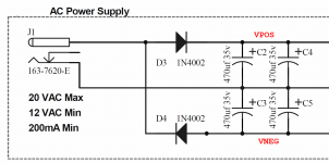
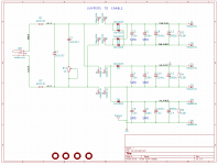
I built up my test board which implements the AC-to-DC power supply found in both the Vendetta Research "transient perfect crossover" and also the NWAVguy's O2 Headphone Amplifier. John Curl refers to the circuit as a Voltage Doubler; a single non-center-tapped transformer secondary produces both +Vdc and -Vdc through a pair of half wave rectifiers. Schematic below; see middle third and lower third.
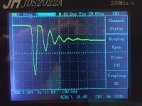
Then I powered it up and began testing it with my brand new JinHan JDS2022A battery powered oscilloscope. This scope has the tremendous advantage that it's completely floating; it has no connection to earth ground. So it can display the waveform of the voltage difference between arbitrary node A and arbitrary node B, while disregarding "ground". Very nice for probing around the rectifier diodes of a transformer-diode-capacitor-regulator power supply.
My findings were:
1. Although you can display the current waveform of the diode, by viewing the voltage across a small valued series resistor (see R1 and R2 in the attached schematic) ... you actually don't want to do this. When the diode shuts off and exhibits non-soft-recovery, its current is near zero (duh). So the behavior of interest is a small fuzzy pimple at the base of a very large current pulse, and it's noisy & low resolution on the scope display.
2. Instead, what you want to do is display the waveform of the voltage across the transformer secondary. Which is easy: just attach the probes! Then you trigger on the spike-down just as the secondary voltage begins to fall from its peak, and Wallah! That's the diode induced secondary ringing. See image 2 below.
3. The 1N4003 is indeed a terrible diode. When driven by the 15VAC wall wart from the O2 headphone amplifier, the first half cycle of its oscillatory ringing is 11 volts tall! Yuck. I personally would lavish care and attention and an extra fifty cents worth of components on the problem, and kill this mosquito with two different bazookas: (a) implement a CRC snubber across the secondary; (b) rip out the 1N4003s and replace them with SBYV27-200 soft recovery diodes. But hey that's just me.
Attachments

I don't think that the ABX protocol of the 1960s has anything to do with the present day audio ABX method. Same title but a very different test.Using the ABX method, participants internal mental processes are different compared for example to an A/B - protocol. That could and did led to different results dependent on the protocol used, researchers did note that already in the 1960s.
............................................................
I don't think that the ABX protocol of the 1960s has anything to do with the present day audio ABX method. Same title but a very different test.
The hardware may be very different. People are probably still pretty much about the same.
Is there something else in particular in mind when you say the test is now very different?
Hi Mark J,
Your power supply circuit isn't designed properly to begin with! No wonder you need special diodes! Tell me, is there anything else you can think of doing to decrease conduction angle, then stand back and complain further about the performance of an otherwise good rectifier diode in a lousy circuit?
What voltages and currents are actually being delivered here? I'll assume (maybe ill advised with this) that this mess is followed by some regulators trying to isolate all that unnecessary ringing from the end circuit. Have you measured the actual peak currents flowing through that poor rectifier diode?
There is one fact that seems to be forgotten when people design this fad driven type of power supply. Regulators have falling performance with frequency, but have no problem at all with low frequencies. By opting for a very short conduction angle, you have pushed much of the noise into very high frequency regions where normal series regulators do not perform well. Why? You are fighting the laws of physics when doing this.
If your end use circuit is supposed to be high quality (not even SOTA), I can't understand why the power supply has been designed with such constraints as this one has. The short conduction angle redefines the requirement of the rectifier to the fast switching type, so even if you persist in designing these supplies this way, you haven't spec'd the rectifier properly. The "corrective measures" you employed would have been part of the normal design had it been done properly.
I'm sorry if I came across strongly, but you are hinting that in the normal use, the 1N4003 is a poor performer. In fact, this is an unusual circuit design that demands a fast rectifier capable of higher current peaks, and mitigation for the inevitable high current spikes created by this design.
A normal circuit that uses 1N400x diodes performs quite well, and using "better" (faster and soft recovery) really doesn't benefit the normal circuit at all.
You are right about measuring the current across a small resistor. The resistor helps to lower the peak current pulses, giving you a low reading even if you manage to get a meaningful reading that way. You can measure across the secondaries, but it would be helpful to use a current probe to see the actual peak currents involved. Of course, those current probes are quite expensive. Still, this is the only way to see the real current waveform. What it would show is the ridiculous amount of current demanded over a very short time interval. That kind of pulse will (of course) excite all reactances in that circuit. Hence all the ringing.
-Chris
I evaluated and even modified F1's for customers. They were typical of digital at the time, but nothing really special. People were always trying to get me to 'improve' them, if possible.
Jan, perhaps you have not read my earlier comments about testing. I, for many years, would do single blind tests, with comparisons between A,B and even C sometimes, making sure that gain and frequency response, and even polarity was kept as close as possible. When I was younger, I passed many of these tests myself, without knowing which was which, until afterward. I impressed the people at Silver (HK) that I could do this, in 1978. However, now almost 40 years later, I use long term listening myself, and I leave the success of my product design to others, who repeatedly give me feedback on my designs, especially audio reviewers, but also serious (about audio quality) customers.
At about the same time that I was so successful with HK, with subjective listening differences, I tried ABX, borrowing an early ABX switching box, and I put it in my own hi fi system at the time. I could not hear any differences, it seemed when the levels, frequency response, and polarity were matched. What an amazing thing? I wrote a couple of LTE's about this to 'The Audio Amateur' about my findings, and perhaps why it happened. I am personally lousy with ABX testing, perhaps worse than average. Why? I hypothesize that it is a change from right brain listening to left brain, that is normally used to get through difficult decisions. I could be wrong, but it is the best hypothesis that I have come up with so far. In any case, I know better than to take a test that I am pretty sure that I will fail, just to be jibed about it for the next 20 years or more, like poor Ivor.
John, appreciate you being so candid about this. There are many things in your post that I would have a comment, and also mainstream accepted explanations to some of your observations.
I don't think they would bring our views closer at this point however, so maybe we should leave it at this (for the time being ;-).
Jan
anatech, I have a feeling you may have forgotten the discussion in post #90664 in which I showed the schematic of the O2 headphone amp's power supply, copied below. John Curl replied in post #90667 that he used that very same circuit with those very same (terrible) diodes in his Vendetta Research "transient perfect crossover". Then we discussed various different ways to display the (terrible) voltage and current waveforms that this supply and these diodes produce.
One idea, attributed to Jim Hagerman (author of an influential paper on snubbers), was to perform the measurement differentially: Use two scope probes and a special scope plug-in diff amp module like the Tektronix 7A22. But Jan Didden didn't like the idea of making room on his bench for an enormous "boatanker" and others objected to its very high price. Other people suggested disconnecting the scope from earth ground using a cheater plug, and then connecting the scope probe's ground clip wherever you damn well please. I suggested that a battery powered scope could probably make the measurements, since it is inherently floating: it has no connection to earth ground. So I taped out the test board and ordered a low cost (USD 115) battery powered scope.
It is true that the test board has no explicit series impedance between the rectifier and the bulk filter capacitor. There's no inductor and no resistor to smear out the current pulse, so the diode conduction angle is low. This is also true in the O2 headphone amp PSU below, and the Vendetta Research "transient perfect crossover". Indeed it is true of 99% of all solid state audio equipment that uses a linear power supply with a transformer and solid state rectifiers. Check Bob Cordell's power amp book Figure 16.1 (68,000uF connected directly to the rectifiers) or Douglas Self's Figure 26.19 (10,000uF connected directly to the rectifiers). For line level supplies check Self's SSAD book Figure 25.1: 4700uF connected directly to the rectifiers. Like it or not, low conduction angle is the overwhelming favorite design approach.
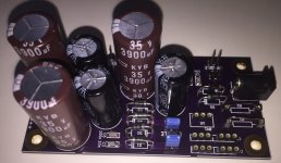
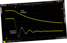
Fortunately the cure is 100% effective and very inexpensive: fit a snubber. If desired, also fit a soft recovery diode. Before and after photos are shown in the Linear Audio article here, I copied one of them (Figure 8) below.
added later: I guess I should mention that I connected 150 ohm, 20 watt load resistors to the test board's DC outputs. The cheapo transformer sagged under load, so the output voltage was about 19.5VDC and the power delivered was about 2.5 watts. This (slightly) increases the diode conduction angle.
One idea, attributed to Jim Hagerman (author of an influential paper on snubbers), was to perform the measurement differentially: Use two scope probes and a special scope plug-in diff amp module like the Tektronix 7A22. But Jan Didden didn't like the idea of making room on his bench for an enormous "boatanker" and others objected to its very high price. Other people suggested disconnecting the scope from earth ground using a cheater plug, and then connecting the scope probe's ground clip wherever you damn well please. I suggested that a battery powered scope could probably make the measurements, since it is inherently floating: it has no connection to earth ground. So I taped out the test board and ordered a low cost (USD 115) battery powered scope.
It is true that the test board has no explicit series impedance between the rectifier and the bulk filter capacitor. There's no inductor and no resistor to smear out the current pulse, so the diode conduction angle is low. This is also true in the O2 headphone amp PSU below, and the Vendetta Research "transient perfect crossover". Indeed it is true of 99% of all solid state audio equipment that uses a linear power supply with a transformer and solid state rectifiers. Check Bob Cordell's power amp book Figure 16.1 (68,000uF connected directly to the rectifiers) or Douglas Self's Figure 26.19 (10,000uF connected directly to the rectifiers). For line level supplies check Self's SSAD book Figure 25.1: 4700uF connected directly to the rectifiers. Like it or not, low conduction angle is the overwhelming favorite design approach.
Fortunately the cure is 100% effective and very inexpensive: fit a snubber. If desired, also fit a soft recovery diode. Before and after photos are shown in the Linear Audio article here, I copied one of them (Figure 8) below.
added later: I guess I should mention that I connected 150 ohm, 20 watt load resistors to the test board's DC outputs. The cheapo transformer sagged under load, so the output voltage was about 19.5VDC and the power delivered was about 2.5 watts. This (slightly) increases the diode conduction angle.
Attachments
Last edited:
Hi Mark,
Lot's of discussion for sure, but I have to pay attention to real life as well. I find that in our chosen field - electronics, we often forget completely about the best practices and realities of circuit design. Using ridiculously high amounts of capacitance isn't the proper way to go. I was hoping you (as the designer) would provide a quick recap of the important figures that drove you to this design. I'm going to believe you didn't simply copy what was done before simply because they were supposed to be "high end", respected designs.
I maintain that the choice of the 1N4003 was in error, given the high frequency operation you are expecting from this rectifier. It wasn't designed for this application for starters, and it is a highly engineered part that has been enormously successful for it's intended application. As such, it enjoys a low (commodity level) price point. This in no way should be construed to mean that it is an inferior part. It is definitely not designed for your application. This is one point that you made that I object to.
I can float my very expensive equipment to make measurements using an isolation transformer, so I'm okay for floating voltage measurements. That, however, isn't what you need to look at. What is the issue is the magnitude of the current pulse. Somewhere around here I have a current probe for high frequencies. Trying to locate it has been an exercise in frustration thus far. The only other actual current probe I have easy access to is one made for DC measurements. It's only good to about 200 Hz, so the wrong tool for this measurement.
Back to the central premise. We are talking about current, then you switched to voltage measurements. These are of use and have value, but do not tell to whole story. Another example of a switch is your test circuit as shown in post 91056 compared to the one referred to in post 91051. Do you see the difference in capacitance used? Are the AC supplies the same, or different?
So just for conversation's sake and referring to the supply in post 91051, what are the design voltages and expected average current demands of the circuit being powered? Are you using active regulation and what type of regulators are you using please? I'm trying to get an idea of how your supply design process worked.
I think another interesting question would be, how much would you say the end circuit was worth, and how would you characterize its performance level compared to similar solutions?
Getting back to my original comment, there were design guidelines laid out for how much capacitance is appropriate per ampere of load current. Today we tend to use higher amounts, but usually only a factor of two for many supplies, followed by regulators of some description. For further proof that these guidelines are still valid, just look at any high reliability equipment in use today. That would be industrial equipment, medical equipment, telephone PBX and <high quality> test equipment. You are not going to see the style of design that was used in your example. Cost was one factor in designing this equipment I listed, but performance and reliability were prime concerns. Nothing even close to what your design type is allowed into space either. That stuff absolutely must be reliable, low noise and high performance. You would think that "high end" audio would follow those examples instead.
-Chris
Lot's of discussion for sure, but I have to pay attention to real life as well. I find that in our chosen field - electronics, we often forget completely about the best practices and realities of circuit design. Using ridiculously high amounts of capacitance isn't the proper way to go. I was hoping you (as the designer) would provide a quick recap of the important figures that drove you to this design. I'm going to believe you didn't simply copy what was done before simply because they were supposed to be "high end", respected designs.
I maintain that the choice of the 1N4003 was in error, given the high frequency operation you are expecting from this rectifier. It wasn't designed for this application for starters, and it is a highly engineered part that has been enormously successful for it's intended application. As such, it enjoys a low (commodity level) price point. This in no way should be construed to mean that it is an inferior part. It is definitely not designed for your application. This is one point that you made that I object to.
I can float my very expensive equipment to make measurements using an isolation transformer, so I'm okay for floating voltage measurements. That, however, isn't what you need to look at. What is the issue is the magnitude of the current pulse. Somewhere around here I have a current probe for high frequencies. Trying to locate it has been an exercise in frustration thus far. The only other actual current probe I have easy access to is one made for DC measurements. It's only good to about 200 Hz, so the wrong tool for this measurement.
I have differential voltage probes, but they are low voltage types I use to look at differential pairs. I think that Jan is justified in his concerns about an expensive instrument that wouldn't get constant use as you would be as well. I don't see why this was brought up in this discussion we are having.But Jan Didden didn't like the idea of making room on his bench for an enormous "boatanker" and others objected to its very high price.
Well, you could have used an isolation transformer as well. A better isolated USB type 'scope is far more capable and would have cost a great deal more than that one did. I'm always very suspicious of inexpensive instruments for what they claim to do.So I taped out the test board and ordered a low cost (USD 115) battery powered scope.
Back to the central premise. We are talking about current, then you switched to voltage measurements. These are of use and have value, but do not tell to whole story. Another example of a switch is your test circuit as shown in post 91056 compared to the one referred to in post 91051. Do you see the difference in capacitance used? Are the AC supplies the same, or different?
So just for conversation's sake and referring to the supply in post 91051, what are the design voltages and expected average current demands of the circuit being powered? Are you using active regulation and what type of regulators are you using please? I'm trying to get an idea of how your supply design process worked.
I think another interesting question would be, how much would you say the end circuit was worth, and how would you characterize its performance level compared to similar solutions?
Just because something functions does not mean that it is the best way to approach a solution.Fortunately the cure is 100% effective and very inexpensive: fit a snubber. If desired, also fit a soft recovery diode.
Getting back to my original comment, there were design guidelines laid out for how much capacitance is appropriate per ampere of load current. Today we tend to use higher amounts, but usually only a factor of two for many supplies, followed by regulators of some description. For further proof that these guidelines are still valid, just look at any high reliability equipment in use today. That would be industrial equipment, medical equipment, telephone PBX and <high quality> test equipment. You are not going to see the style of design that was used in your example. Cost was one factor in designing this equipment I listed, but performance and reliability were prime concerns. Nothing even close to what your design type is allowed into space either. That stuff absolutely must be reliable, low noise and high performance. You would think that "high end" audio would follow those examples instead.
-Chris
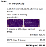
Here are the Gerber files for the PCB in zip archive format; please feel free to build one or more boards and make all the measurements you desire. The file name extensions are set to OSH Park's standard; if you need a different set of file extensions (e.g. for Elecrow or seeed or some other PCB fab), just let me know. I will run a simple MSDOS .BAT file that executes the REName command once for each PCB layer.
OSH Park ships boards in multiples of 3 copies. This will give you the opportunity to stuff three boards with three different choices of capacitor values and experiment with conduction angle.
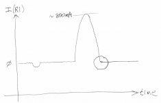
When you do start displaying current waveforms you'll see something like my pencil drawing below. Big current pulse when recharging HW+ which is loaded by 150R. Small downward current pulse when recharging HW- which is loaded by 6.8Kohms. The not-soft-recovery ringing is within the circled region and is very low amplitude compared to the peak of the current wave. Getting your display instrument to zoom-in upon the little wiggles inside the circle, is not going to be easy. BTW in my testing, I found that R1 = (1/3)*(secondary DC resistance) gave the best display. Smaller than that, the amplitude was severely degraded. Larger than that, the current sense resistor began to affect the Q of the resonant circuit. But maybe your setup with your choices of capacitance, will require different resistance values. Try it and see!
_
OSH Park ships boards in multiples of 3 copies. This will give you the opportunity to stuff three boards with three different choices of capacitor values and experiment with conduction angle.
When you do start displaying current waveforms you'll see something like my pencil drawing below. Big current pulse when recharging HW+ which is loaded by 150R. Small downward current pulse when recharging HW- which is loaded by 6.8Kohms. The not-soft-recovery ringing is within the circled region and is very low amplitude compared to the peak of the current wave. Getting your display instrument to zoom-in upon the little wiggles inside the circle, is not going to be easy. BTW in my testing, I found that R1 = (1/3)*(secondary DC resistance) gave the best display. Smaller than that, the amplitude was severely degraded. Larger than that, the current sense resistor began to affect the Q of the resonant circuit. But maybe your setup with your choices of capacitance, will require different resistance values. Try it and see!
_
Attachments
Last edited:
I don't think that the ABX protocol of the 1960s has anything to do with the present day audio ABX method. Same title but a very different test.
If ABX is used then it still is ABX.
")
Although the original test protocol didn´t allow participants to relisten to the samples in whichever way he wants - what the later invented ABX comparator (and todays software solutions) do - it still remains to be the same task. Listen to A, listen to B, listen to X and decide whether X is A or B .
You may reverse the order of listening to A and B, but if you are not doing what i´ve described above then you are not doing an ABX-test.
Of course there are good reasons for choosing other protocols, but it depends on the hypothesis examined. That´s why i emphasized the importance of clearly stated research hypothesises and to choose an appropriate test protocal afterwards; to use ABX just because someone else did it wouldn´t be a sensible decision.
The sony chips I worked with back then were a 9 bit and then a 7 bit add on following Stockhams design. So quoted as 16 bits but was really 9.
According to the service manuals of the PCM-F1 it used monolithic converters (of the dem variety if i recollect it right). Even only one DAC used for both channels so introduced the usual half sample delay between channels, which was afaik confirmed to be detectable later.
- Status
- Not open for further replies.
- Home
- Member Areas
- The Lounge
- John Curl's Blowtorch preamplifier part II