That PDF was a contribution of a forum friend called RAJ.
I do not know his name is this forum...but it seems he do not want to show himself off.
Nice work he did.....also Klaas may be cooking something in his home.... after some beer in this saturday he may appear Sunday to tell us something.
Greg is a guarantee...will make a very good one..for sure.
Good weekend friends, as i know many of you use to disappear during weekends.
Dx amplifier is beeing constructed in the Brazilian forum i use to visit too....i am glad about that...of course.
regards,
Carlos
Nordic said:Shame on you Greg, I am officialy classified by my government as previously advantaged....i.e. screwed from here on ad finitum....
Nordic, does that mean you have to wash your own car now. hahaha. When I was working in the engineering game, there were lots of South Africians involved. I even had a South Africian girl friend, so I've heard lots of stories from all perspectives, very complicated situation.
I'm looking forward to seeing the cleaned up PDF, RAJ did a very good job. I still have a bit to learn.
regards
K here it is, cleaned up and with fatter pads..
Orientation is right for photoetching, think you have to flip it for toner transfer...
Print at 300dpi, you dont have to extract the file just open in in winzip or winrar, select it by clicking with right mouse button, and click print file. It came out fine when I tested this procedure now...
Orientation is right for photoetching, think you have to flip it for toner transfer...
Print at 300dpi, you dont have to extract the file just open in in winzip or winrar, select it by clicking with right mouse button, and click print file. It came out fine when I tested this procedure now...
Attachments
During weekends, Dx amplifier will provide you fuel economy
You will be inside your home...listening with pleasure....you wil not answer to phone ringing...and in special, your car will be keept inside garage.
Not running the car...fuel economy!...another advantage of the Dx amplifier compared to others.
hehe
Be Happy folks....i am!
regards,
Carlos
You will be inside your home...listening with pleasure....you wil not answer to phone ringing...and in special, your car will be keept inside garage.
Not running the car...fuel economy!...another advantage of the Dx amplifier compared to others.
hehe
Be Happy folks....i am!
regards,
Carlos
Attachments
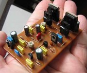
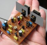
Dx amplifier was made thinking about you.
As old computer heatsinks are easy to find...also computer small fan blowers...they are cheap.
Beeing very small, you can install 6 units inside to produce a nice home teather.... or amplifiers using input filters working as crossover....one for bass, other for treble and other for mids.
Also small enougth to be included inside automobile amplifiers that already have switching power supplies.
Small to be included inside a speaker enclosure, to produce an ative speaker.
Very small boxes can be made...Dxyingclone can be produced.
regards,
Carlos
Attachments
One simple input circuit, something alike this one...adjusted to work
fine to your personal needs...will provide you the multi frequency amplification.
100 Watts can be produced using 35 volts symetrical supply...and even more including more output transistors (with emitter resistors) and bigger voltage supplies.... this may produce two nice bass units.
Other four amplifiers, working over 8 ohms, a very standard Dx units will provide you more 200 watts of nice sonics amplifier.
Minimum power of 600 watts can be constructed, Ximple and Xcheap!
regards,
Carlos
Attachments
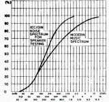
Audio spectrum..of modern music says that...
Power proportion of music is around
50 percent for woofer
35 percent for mids
15 percent for highs.
Beeing this way...Dx amplifier in a multi frequency system, will fit fine.
Also audio quality is extremelly better when using dedicated amplifier into a reduced bandwidth...less distortion and higher quality of reproduction...also amplifiers can be tweaked to turn optimum their reproduction into some pre decided range of frequencies.
Separating speakers, you will be inside the orchestra...a real surrounding system....instruments will came from different directions.
The speaker price will be lower, as you may choice lower power units...matched with the bandwidth needed.
Small speakers, used to Mids and treble can he hidden..to avoid problems with your wife...beeing low powered (because of power proportion you have inside modern music) you will be able to use very thin wires to run your system...do not worry with capacitances.... Dx amplifier is stable with 2.2 uf conected into it's output...so...some picofarads will not turn it unstable or will make it reproduce mufled sonics.
The use of small heatsinks...computer chips heatsinks, will provide you noiseless fan blower work..also fan can work with reduced voltage...for example....8 Volts DC.
regards,
Carlos
Attachments
I'm playing around with a vbe-multiplier now, mounted on main heatsink.
Trying to bias much higher now - before i biased at 30-40 mA , now i'm trying ~80 mA.
It doesn't seem to stabilize.
Also i noticed when driver-temperature goes up, bias goes up.
The thermal compensation is probably not tracking fast enough (it takes a lot of time for the main heatsink to heat up when bias goes up, so the thermal compensation is reacting too slow).
Only solutions i can think of now is mount thermal compensation to driver(s), or mount drivers to main heatsink.
Any thoughts ?
With kind regards,
Klaas
BOM for PCB in post 503
C2, C4, C7, C8, C11, C13 .1u 5mm film 12
C15, C16, C22, C23 .1u 5/10mm film 8
C17 .1u 15-25mm film 250v 2
C9 12p 5mm film np0/c0g 2
C5 220p 5mm film 2
C10 220u 5mm elco 16v 10mm dia. 2
C18, C19, C20, C21 4700u 10mm elco 50v 30mm dia. 8
C3, C6, C12 47u 5mm elco 50v 10mm dia. 6
C1 4u7 17mm film Width 6mm 2
C14 5p6 5mm film np0/c0g 2
VR1 10k 5mm x 2.5mm trim. top adjust 35V - +-7K7
VR2 100 5mm x 2.5mm trim. top adjust
R22, R23 10 2w 4
R16, R17 33 0.25 4
R15, R18 82 0.25 4
R4, R8 100 0.25 4
R 19 120 0.25 2
R 14 220 0.25 2
R 9 820 0.25 2
R26, R27 10k 2w 4
R 5 1k 0.25 2
R24, R25 1R 1w 4
R2, R6 2k2 0.25 4
R 10 1K8 0.25 35V - 1k8 2
R 12 2k2 1w 2
R 13 2k7 1w 2
R3, R11 39k 0.25 4
R7, R20, R21 4k7 0.25 6
L1 27turns of .6mm enemal wire 2
Q1 2n5401 Alternatives: BC556, BF423, BC556 and BC640*
Q2 2n5401 Alternatives: BC556, BF423, BC556 and BC640*
Q3 TIP41 NPN (VAS) Alternatives: BD139
Q4 TIP41 NPN Alternatives: BD139, MJ340, TIP31
Q5 TIP42 PNP Driver Alternatives: BD140, MJ350, TIP32
Q6 2SC5200 NPN Output
Q7 2SA1943 PNP Output
Z1 1N4742 12V Zener diode – 200mW or more
Now you see why i runned out from those things.
To make it simple and less problematic.
Related all those things... my first preference is to give to the output transistors, heatsink more than enougth...and to help with a fan blower to double guaranteed to drive the amplifier hard.
My second decision is those diodes, because they have more junction to reduce bias under thermical action.
Third is to intall the VBE multiplier into the heatsink..the good place for it as you know Klaas.
The fourth idea, may work fine...BUT...will be awfull that transistor over the other (maybe imoral..ahahaha!)
Maybe a negative coeficient resistance may help, if placed in the VBE base.
You choice the better option to you.
regards,
Carlos
To avoid those bias drift, because of the drivers...install
Small heatsinks on them.... as the temperature rise that interest us, to produce action over the VBE multiplier, is the output temperature.
Of course you already perceived that...not too much intelligent decision from me....hehe
Force those guys to be cool!
regards,
Carlos
Small heatsinks on them.... as the temperature rise that interest us, to produce action over the VBE multiplier, is the output temperature.
Of course you already perceived that...not too much intelligent decision from me....hehe
Force those guys to be cool!
regards,
Carlos
Attachments
The "L" shape one is very pretty too.
There's a lot of nice shapes that will match the needs there.
Dinaminc Power there, will not go over 1.5 Watts each driver...so... 1 square inch is enougth to each one of them.
If you decide to use "L" shape or something better, you will be able to reach a heatsink capacity that will be more than double than one suggested by that flat square inch aluminium plate.
" Dx amplifier is Hot "
regards,
Carlos
Attachments

Hi Carlos, the parts are the ones you mention, in your posts, and schematics, it has a few extra components like the PSU caps etc... but the majority of stuff is directly your circuit and suggestions...for the 35V version.
I just inlcuded lead pitch too to make organising the parts easier...
I cant find 5mm 5p6 cap anywhere online localy... must still check Farnels, I can order from them through a local co... Is that the exact value needed or can slightly larger or smaller value be used if I find one?
Have to read a few more posts to see what transistors you used in then end...
You can increase this capacitor, that Miller one, till maximum of 27 picofarads,
People say that Silver Mica is more stable...well...sonically i could not perceive that ...as this is very subtle to ear perception.
I am using Ceramics...and you can stole from your FM receiver....hehe...better another board you have as junk.
10 picofarads is very common in radio frequency things, as oscilators and FI transformers.
12, 15, 18, 20 and 22 are easy to find too.
Used capacitors are tested capacitors.. the voltage swing there will be the maximum output voltage swing (less than)...just check if the unit can hold the voltage..having doubts..install from the plus 35 to the negative 35 and wait some seconds..if not hot or not explode...hehe...it is good enougth related voltage tollerance....Silver Mica material is more stable when face variable voltages...and those ones, there, are reasonably big.
In my simulator.... sinusoidal waves started to turn triangle, at 42 Kilohertz, when i have used something alike 47 picofarads...but less than 22 send that waveform distortion to outside our worries limits.
Relax, as i have checked that the amplifier works fine without that Miller capacitor..it is there not to produce too much scandall into people.
That one at the feedback line...hehe..if you remove, the amplifier will oscilate till it's death!
regards,
Carlos
ahh, so the vbe-multiplier is less effective because you have less diode-junctions to counteract the effect of heating up of drivers/outputs.
Sounds to me like complicating the thermal compensation creates problems instead of making behavior better.
I will switch back to the 3 diode-solution and increase heatsinking on the drivers.
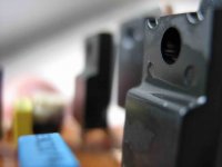
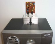
Completely off-topic (hope you don't mind), refurbishing a pair of these has kept me occupied the past few days, making progress on the DestroyerX-amp almost zero:
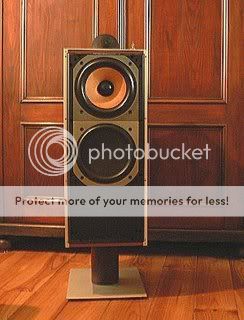
Picked them up cheap (tweeters were shot ,had to fit other tweeters)
Considering their age, they sound pretty awesome (look at the datestamp on the woofer):

with kind regards,
Klaas
Sounds to me like complicating the thermal compensation creates problems instead of making behavior better.
I will switch back to the 3 diode-solution and increase heatsinking on the drivers.
Completely off-topic (hope you don't mind), refurbishing a pair of these has kept me occupied the past few days, making progress on the DestroyerX-amp almost zero:
Picked them up cheap (tweeters were shot
,had to fit other tweeters)Considering their age, they sound pretty awesome (look at the datestamp on the woofer):
with kind regards,
Klaas
- Status
- Not open for further replies.
- Home
- Amplifiers
- Solid State
- Destroyer x Amplifier...Dx amp...my amplifier