Crazy uncle Charly, I could never do that to my lenses...
I have some nice vintage gear...
http://smg.photobucket.com/albums/v497/Nico2000/Colour/
Some of my pic... the pic called macrob6x8 has a clearly visible grain of sand in a small pink shell, the little white segments are about 2mm long each.
the webcam can zoom close enough to show fingerprints too, just not enough light here... so the pics are horrible... also holding it by hand.
I am getting a headache trying to figure out just how my little amp actualy works end to end, been reading stuff all daay long...
Learned so much, but not what I needed, sigh
Thanks Nordic...also if i can help you to understand how those things works
go directly to my mail and i will go with you travelling into the circuit dressed, both of us, as electrons.
Good to see your images.
Negative to destroy such a good camera...talking about those simple machines that return to you after made your photographs..those simple Kodaks of no return..lenses are there to be used..plastic lenses.
Good that your WEB camera is making focus...but resolution do not let us to apreciate focusing things.
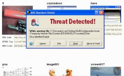
I have received a gift, when visiting your Photo Bucket....a nice virus that i will eat with catchup...do not worry..i know what to do with those things.
I am a "fully transistorized guy"...no chips or Fets in my life.... BGT transistorized amplifiers, even the most full of gadget ones will be "my beach"...and related those ones i can help you...but out of my limited "transistorized" knowledge i cannot help.
regards,
Carlos
go directly to my mail and i will go with you travelling into the circuit dressed, both of us, as electrons.
Good to see your images.
Negative to destroy such a good camera...talking about those simple machines that return to you after made your photographs..those simple Kodaks of no return..lenses are there to be used..plastic lenses.
Good that your WEB camera is making focus...but resolution do not let us to apreciate focusing things.
I have received a gift, when visiting your Photo Bucket....a nice virus that i will eat with catchup...do not worry..i know what to do with those things.
I am a "fully transistorized guy"...no chips or Fets in my life.... BGT transistorized amplifiers, even the most full of gadget ones will be "my beach"...and related those ones i can help you...but out of my limited "transistorized" knowledge i cannot help.
regards,
Carlos
Attachments
Wow Carlos that is strange, wonder if that is why photobucket was unreachable yesterday...
http://www.diyaudio.com/forums/showthread.php?s=&threadid=98674
I started a thread... feel free to jump in with explanations, suggestions, answers etc..
Can I use 10000uf caps on those boards from pdf? Otherwise I need to buy the 4700uf caps... allready have the 10s...
http://www.diyaudio.com/forums/showthread.php?s=&threadid=98674
I started a thread... feel free to jump in with explanations, suggestions, answers etc..
Can I use 10000uf caps on those boards from pdf? Otherwise I need to buy the 4700uf caps... allready have the 10s...
Nordic said:Greg, don't be so cheap, just make the board bigger!!!!!!! I stilll have to get a soldering iron in there you know... And I have seen carlos' stuff he solders with welding rods....
Hi Nordic,
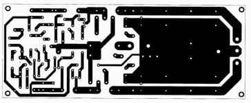
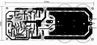
The size of the PCB is related to the EURO FORMAT PCB 160 mm x 100 mm, so if I can fit 2 into that size it works out cheaper. Currently these boards are a little under 100mm x 80mm.
regards
kvholio said:Greg, good to see your pcb-design
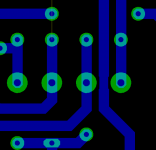
Just a small remark: Clearance under c12 seems very small, would it be possible to use smaller solder-pads for c12 to increase clearance ?
Hi Klaas,
Yeah, I really hate the route of that trace. I designed all my components to have reasonably large pads because the PCB is single sided and I like to use a big soldering iron.
I could make a custom component or make the trace a little smaller when it passes under C12.
regards
Attachments
Graham Maynard said:Hi Carlos,
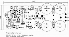
Component size is related to manufacturer and what it is possible to obtain in whatever part of the world the amplifier is constructed (welded). 250VDC is likely to be tough enough for for a typical domestic amplifier.
This is a pic from my amplifier prototype.
The 250V red C has 10mm lead spacing; the R is a non-inductive thick film (TO220) with 5mm spacing.
The other red Cs are 470nF@63V.
I would agree with making the PCB a little larger; not everyone can easily obtain the exact sub miniature parts necessary, and a more generously spaced layout helps novices to follow (understand) the circuit. After-all, size does not affect reproduction quality as much as an incorrect compact one could.
The star ground needs priority, and that means several tracks.
(Should be called an 'octopus' ground !)
Cheers ......... Graham.
Hi Graham,
Thanks for the info and the picture. I'll try to make provision for multiple sized caps and lead spacings. People could mount "normal" sized components on the front and big ones on the back. Looks like I'll have a link or wire back to star earth for the zobel earth connection.
Please see me explanation a few posts back about the size of the PCB, cost is an important consideration here. 2 PCBs for $25 from OLIMEX in 1 off lots sounds worthwhile. I take your point on "incorrect compact" designs.
Still working on the 'octopus' earth.
It may look more like a squid though. regards
Greg
Nordic said:Hmmmmmmmmm seafood... except I don't eat musscles and other bait...
Think I will start off on the pdf version, and then just transfer the parts to the Olimex boards when they are done, If you want to get the 2 boards from Olimex for $25, I would gladly take one...
Ooops...just double checked, $26...sorry.
A prawn zobel sounds nice (i.e. shrimp).
Greg Erskine said:
Ooops...just double checked, $26...sorry.
Greg
Are you getting some PCBs done? If so, I'd like to get in on the action with a pair.
rabbitz said:Are you getting some PCBs done? If so, I'd like to get in on the action with a pair.
Hi rabbitz,
It's a little early yet, we still need to "prove" the PCB is OK.
Thanks
Nordic said:Ok, I'll ask my wife for 50c
You need a dollar, one shiny US dollar that is.

- Status
- Not open for further replies.
- Home
- Amplifiers
- Solid State
- Destroyer x Amplifier...Dx amp...my amplifier