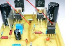
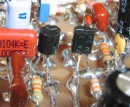
Pretty...very pretty construction...the best one made with Dx schematic
One day i will have a photo machine so good as yours.
Very good image with only 32K....very impressive your digital machine.
Tell me some about those heatsinks... are they enougth?
I was observing details... the screw positions are almost the same..perfect alignment of transistors.....very nice job.
regards,
Carlos
Attachments
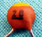
Please, i would be happy to know the meaning of this yellow mark here
Are there someone that can inform me.
Is this precision mark?
Voltage limit mark?
I have found this capacitor in a Japanese circuit...constructed around the eigthies.
regards,
Carlos
Are there someone that can inform me.
Is this precision mark?
Voltage limit mark?
I have found this capacitor in a Japanese circuit...constructed around the eigthies.
regards,
Carlos
Attachments
Wakarimashita....thank you Jacco...you!...you!..you!
A very nice guy.
So des ne!... domo arigatô gosai mashita.
Tântalum?..... grumpf!!!!
I am kidding...very happy with your presence..the image is only to produce "noise"...this is atractive to many folks that loves to have some fun.
regards,
Carlos
A very nice guy.
So des ne!... domo arigatô gosai mashita.
Tântalum?..... grumpf!!!!
I am kidding...very happy with your presence..the image is only to produce "noise"...this is atractive to many folks that loves to have some fun.
regards,
Carlos
Attachments


Wow, the heatsinks are pretty expensive!!!
Would 25V rails make it possible to use sinks more like the ones I posted... ? How many watts would that give into 8 ohms?
I think the sinks, the transformers, and those 8 rail caps will be very expensive all added together.... It better sound good, and not burn too many components while I set it up.
Also havein hard time getting the 2SA1943, can get 2 but I need to order Ex the UK... Do any transistors need to be matched - I need to know so that I can order enough?
Is the Tip41s better than bd139s.... the bd139 is only rated for 12W.?
Which transistor package should the Qs be? i.e. A B C.....?
LOOK ! I AM YOUR FATHER!!!!!!!!!
Attachments

Ahahah!...very nice image you have produced..funny!
You told me you are a very clever fisherman..thank you by the image you have sent me dear nephew Nordic.
Do you want me to adjust the amplifier to your 25 volts...i will do it gladly.... the "By Nordic" amplifier can be produced that way?
Just tell me... i will do it for you ....for free...and very happy!
It seem "Dart Wader" helmet.... the dark side....hummm...nice those things... i like that.
Yuuuuuuuhúuuuuuu!
regards,
Carlos
Attachments

My dear Dx Amplifier Pioneer.... dear Klaas...if possible, more images from your
amplifier...please.
It can be used in our thread...this one.... there are people that do not read any entire thread..so...if i produce hundred images...they will think that 100 folks have produced..this may help them to decide to do this amplifier too...of course!... i will be happy with more friends using it.
If you prefer..send them big..i can resise them to reduce, also i can crop to make many images from a single one.... will depend from your resolution....the biggest will be better, as i will crop small portions.
Our thread is having good hits...and 20 thousand for one guy constructing... we have to make if interesting to obtain more 20 thousand..so... i will have one more constructing.
Thanks in advance,
Carlos
Here is your answer Nordic.
My Word program is blocked....grrrrr!..so, i will try to attach wave pad file:
You power will be exactly 30 watts rms over 8 ohms
Your rail current will be 870 miliamperes.
Your off set will be near 1 milivolt with the off set
trimpot adjusted to 3380 ohms
If you decide to use VBE multiplier, the base to emitter
resistance will be 620 ohms (ajustable) and the base
to colector will be 1800 ohms (fixed one)
Over 4 ohms your power can be 60 watts rms...this
will depend from your supply...if it will hold those 25 Volts
or not...or...how many volts it will loose when hard drained
BD139 is vastly better than TIP41...but power there will not
be a problem.... use small aluminium heatsinks...for VAS
and for the drivers 15 milimeters sides for Vas... and make
a "L" shape from a 30 milimeters to 20 milimeters aluminium
to the drivers.
Matching is extremelly important to the input differential...but
Dx amplifier will work fine even using mismatched ones..the off
set adjustment will compensate a little that mismatch.
Also good for Drivers...also interesting to output...but difference
around 30 percent are not so bad in real world.
You can use TIP41/42 to your output..but only using 8 ohms ,
and having good heatsink..they will be near their limits and will
need to work not so hot.
Also TIP3055 and TIP2955 can be used for output...other TIP transistors
can be used too...also, the amplifier can be modified to accept
TIP142 and TIP147 if needed.(using 25 volts of even more)
Well...good...Wavepad worked fine here.
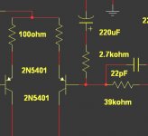
Observe that in the feedback line, you will need to replace a resistance..using the one show in the image supplied.
Also, do not worry with rail condensers...you can replace all them to 100uf..also your supply will work fine with 4700uf each rail
If you decide to use diodes to control the bias...use three units and a 150 ohms (adjustable) resistance in series with them...every silicon diode will fit...1N4148, 1N4001 and up.
regards,
Carlos
My Word program is blocked....grrrrr!..so, i will try to attach wave pad file:
You power will be exactly 30 watts rms over 8 ohms
Your rail current will be 870 miliamperes.
Your off set will be near 1 milivolt with the off set
trimpot adjusted to 3380 ohms
If you decide to use VBE multiplier, the base to emitter
resistance will be 620 ohms (ajustable) and the base
to colector will be 1800 ohms (fixed one)
Over 4 ohms your power can be 60 watts rms...this
will depend from your supply...if it will hold those 25 Volts
or not...or...how many volts it will loose when hard drained
BD139 is vastly better than TIP41...but power there will not
be a problem.... use small aluminium heatsinks...for VAS
and for the drivers 15 milimeters sides for Vas... and make
a "L" shape from a 30 milimeters to 20 milimeters aluminium
to the drivers.
Matching is extremelly important to the input differential...but
Dx amplifier will work fine even using mismatched ones..the off
set adjustment will compensate a little that mismatch.
Also good for Drivers...also interesting to output...but difference
around 30 percent are not so bad in real world.
You can use TIP41/42 to your output..but only using 8 ohms ,
and having good heatsink..they will be near their limits and will
need to work not so hot.
Also TIP3055 and TIP2955 can be used for output...other TIP transistors
can be used too...also, the amplifier can be modified to accept
TIP142 and TIP147 if needed.(using 25 volts of even more)
Well...good...Wavepad worked fine here.
Observe that in the feedback line, you will need to replace a resistance..using the one show in the image supplied.
Also, do not worry with rail condensers...you can replace all them to 100uf..also your supply will work fine with 4700uf each rail
If you decide to use diodes to control the bias...use three units and a 150 ohms (adjustable) resistance in series with them...every silicon diode will fit...1N4148, 1N4001 and up.
regards,
Carlos
Attachments
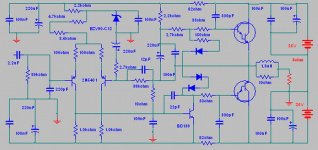
Here is a simulated version of the Dx amplifier...darlington version
Dx amplifier can be customized to your parts and your needs.
Just inform what you want.
This one is not the Standard, guaranteed version.
Just an option for darlington owners.
Related darlingtons.... you cannot tweak the internal resistances, this limits adjustments you can make on them...normally they distort more and "loves with passion" to oscilate.
I do not think they are a very good idea...but...you may have them...so...there's the option.
Include big condensers from the colector to the base in your darlingtons....TIP142 and TIP147 may hold the 50 watts amplifier, BUT using 8 ohms only...they are 100 watts maximum i think...so...will not be able to hold 4 ohms load using plus 35 and negative 35 (or another voltage around those)
Using 25 volts symetrical supply you may use 4 ohms....but will be dangerous, as will work sligtly over the limits...short life in this case i think.
This darlington version, absolutelly, is not guaranteed...do it under your own risk...was only simulated...real life may explode!
Yes!...a capacitor connecting those darlington bases is a good idea because those diodes..... 1uf, or more, will be good.
regards,
Carlos
Attachments
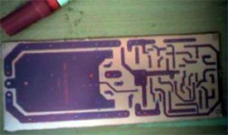
You can do your own board using hand work
Watching your schematic..... draw it over the copper....then...erase the components..keep the lines only.
Put it into the acid to corrode...then clean it and solder your parts directly over the copper lines.
You will be watching the circuit...made the same as the schematic.
Nothing can he more fast and more easy than that.
regards,
Carlos
Attachments
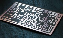
And this kind of construction is not so ugly as you may imagine
Depending the solder quality,..circuit lines can be made very interesting.
Solder in my country is not expensive....A pound of the Best one, will cost under 15 dollares (US dollar).
That solder brand is "Best" and has triple flux of solder resine inside de solder wire, 1 milimeters diameter and coiled over a plastic reel.
regards,
Carlos
Attachments
This is very good Graham... i loved to listen what you said..or to read to be more
precise with words.
I will produce more funny pictures, and i will try monocle too.
Problem is that damn Canon A430...it is so crispy related images that is turning me more and more old.
I am near 55.... very close to be mumified.
You know what i mean..those Egiptians conserved for ethernity inside Pyramides....Queops, Quefren..and others.... i am turning old and ugly...
Watching myself in front of the mirror my mind construct the idea of "Ptolomdex the last"
Brazilians will be the future owners of fuel resources...so.... here is the image of Sheik Al cohool
regards,
Carlos
Attachments

Lovely etching material Nordic.
Thanks to construct this amplifier.
Very kind from you.
I am happy as this image shows you...it is animated, but i do not know if movement will be blocked in our forum.... well clicking over the image, the Dx chicken will dance.
regards,
Carlos
Thanks to construct this amplifier.
Very kind from you.
I am happy as this image shows you...it is animated, but i do not know if movement will be blocked in our forum.... well clicking over the image, the Dx chicken will dance.
regards,
Carlos
Attachments

- Status
- Not open for further replies.
- Home
- Amplifiers
- Solid State
- Destroyer x Amplifier...Dx amp...my amplifier