You've been reading too many Bybee adverts.
Yes. The damage has been done and I see no reason for repair.
Poor Audio
Control Theory is a simple theory. There is not even a simple theory dedicated to the audio field. The narrow incompetent Control Theory doctrine with its terminology has been imported and (mis)applied to audio amplifiers handling demanding complex signals. Control Theory prescribes a monstrous amplification factor as the avenue toward linearity, that is to say, voltage regulation accuracy. High voltage regulation accuracy has paradigmatically become to mean low audio signal distortion, feedback constituting a cheap all in one cure for a ragbag of malaises. Following the principle, audio amplifiers have been extensively designed as a voltage regulator, balanced operation in closed loop as a central topological feature, and further equipped with series regulators, parallel regulators, current regulators, current mirrors and capacitance multipliers.
Feedback control stabilizes the operating point against variations in amplification, temperature and loading, hence is of practical importance. Feedback inhibits the system response, causes havoc in the signal development, introduces instability, increases the phase disorder and infects the amplifier with the poisonous farrago of resonant switching and ferromagnetic saturation.
The Transfer Function is a classical control theory*, a linear time-invariant system in equilibrium, where the sinusoidal voltage and current waves persistently oscillate at the same frequency with constant phase, maximum amplitude, zero potential energy, zero noise, and zero energy lost. The transfer function describes an unrelated input-output relation without finesse, the output value being the same for every input value, not using any knowledge of the interior structure of the physical system - good enough for DC-gain evaluation of operational amplifiers.
The operational amplifier was intended to control industrial plants, as a regulator in a servo system compensate for machine motion errors, keeping designated signals supplied by sensors within a prespecified range as the only task. The parameters of the ideal operational amplifier were ambitiously finalized as infinite gain, infinite bandwidth, infinite input impedance, infinite slew rate and zero output impedance, aiming for a combustible DC-to-DC converter. Operational amplifiers furnished with these discordant characteristics are considered to produce a pure sinusoidal steady-state response to a pure sinusoidal steady-state input at the same frequency. Large amplitude and low intrinsic resistance promote voltage regulation capability while comparing sensor output with desired input and adjusting input accordingly by producing a voltage proportional to a single, clearly identifiable error. Determining all the transfer parameters, negative feedback incarnates the transfer function, the open loop being outside the scope of interest.
* Unlike the popular Fourier Transform, which is a state-space representation based on the one-dimensional simple harmonic oscillator, or alternatively, a conceptual and semantic mumbojumbo.
"Control Theory is a simple theory"
Only insofar as audio is concerned. I think you will find that it is one of the more difficulty areas of mathematics - and not because Douglas Self says so. There is a good infographic (sorry, cannot locate it at the minute) that shows the difficulty (=intellectual challenge) of various branches of mathematics and fields of study that rely heavily on advanced math. Tensor calculus is about a third to half way to the most difficult stuff (Einstein used this i.a.o. to develop his equations for GR) and someway beyond this is control theory.
Control theory as applied to audio is an exceedingly simple application of the science, but once you get into large, intricate systems, it becomes very complex and many of the problems cannot be solved without lots of computing power. Beyond this, most difficult areas cannot be solved by humans and will ultimately rely on AI and huge amounts of computing power. I will try to dig up the infographic - I saw it about 6 months ago.
Chris,Here's the math you requested.
Thanks for having taken the trouble to come with this calculation.
Unfortunately I'm too busy now to react before Wednesday, but I will certainly come with a reply.
A mathematical correct expression is a universal way to cover the subject in how far Ro or even hfe are able to disfeature the CFA concept.
And I have absolutely nothing against sims and as a matter of fact, this could most likely also be simmed with mathematical modules.
Hans
So the latest pronouncement regarding CFA’s is that they are the product of occultist science?
I always knew there was a bit of the devil in me.
Yeah , just like the last CFA big thread. Either argue the semantics into infinity ...
or design 10 CFA's and 10 VFA's to see whether it even matters. (I did that 2 years
ago).
All 20 "slewmaster' CFA/VFA's were nearly identical sounding and rock solid.
Some designs favored some systems (loudspeakers) , but only in very minor aspects.
So , off we go again "nickle/diming" the theory to death and trying to create
something out of nothing (again).
 )
)I must thank the last group of "nickle /dimers" for giving me a freaking headache
which triggered me to design a whole bunch of amps.
2 cents ain't worth squat.
Ain't got time for this 'old tech' anymore (class G or D + SMPS = 21'st century).
Edit- this thread is like "blowtorch 2".
OS
OS
One last try
For CPaul
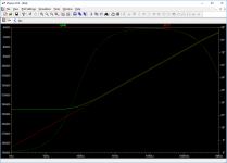
I spent (hopefully not wasted) my time this morning making a little sim. This is the simplified CFA circuit very similar to the one on the AD844 datasheet, made with BC550 and BC560 transistors (because I just moved stuff around on something else I was working on). This does not really matter.
This is connected as a voltage follower with a 1K Rf and the amp is compensated with 100pF so that the parasitic capacitances don’t matter. The inverting input current is monitored by a series voltage source. The green plot is current in the inverting input and the red plot is current in the compensation capacitor. The green plot is the open-loop transimpedance analogous to the open-loop gain in a VFA. You will see a DC value of -144dB (~15.8Meg transresistance) this is totally determined by lost current due to process beta and early voltage, super cascoding and other tricks like base current recovery could raise this considerably (see for instance the AD846) and move the low frequency break point around. It is at 0 degrees so it is not “positive feedback”. If I turned it into a VFA with 1K degeneration I would get an Aol of ~15.8k.
The two curves join as frequency is increased and the two currents are equal and at 90 degrees i.e. the current into the inverting input fully accounts for the displacement current in the comp cap and there is virtually nothing left over. You can eyeball about -104dB at 10kHz and do the math (2Pi*f*C). The point is the low frequency break point and DC value are essentially as unimportant as the DC open-loop gain of a VFA and its break point. A VFA voltage follower with an AOL of 10**7 is not 10X better than one that has 10**6.
For CPaul
I spent (hopefully not wasted) my time this morning making a little sim. This is the simplified CFA circuit very similar to the one on the AD844 datasheet, made with BC550 and BC560 transistors (because I just moved stuff around on something else I was working on). This does not really matter.
This is connected as a voltage follower with a 1K Rf and the amp is compensated with 100pF so that the parasitic capacitances don’t matter. The inverting input current is monitored by a series voltage source. The green plot is current in the inverting input and the red plot is current in the compensation capacitor. The green plot is the open-loop transimpedance analogous to the open-loop gain in a VFA. You will see a DC value of -144dB (~15.8Meg transresistance) this is totally determined by lost current due to process beta and early voltage, super cascoding and other tricks like base current recovery could raise this considerably (see for instance the AD846) and move the low frequency break point around. It is at 0 degrees so it is not “positive feedback”. If I turned it into a VFA with 1K degeneration I would get an Aol of ~15.8k.
The two curves join as frequency is increased and the two currents are equal and at 90 degrees i.e. the current into the inverting input fully accounts for the displacement current in the comp cap and there is virtually nothing left over. You can eyeball about -104dB at 10kHz and do the math (2Pi*f*C). The point is the low frequency break point and DC value are essentially as unimportant as the DC open-loop gain of a VFA and its break point. A VFA voltage follower with an AOL of 10**7 is not 10X better than one that has 10**6.
Attachments
Last edited:
For CPaul
I spent (hopefully not wasted) my time this morning making a little sim.
Thank you. What do you believe that you need to convince me of?
Thank you. What do you believe that you need to convince me of?
That ro and beta don't matter and the "not a pure transconductance" argument makes little sense.
Can you forward the spice file?
To convince someone that you are right, the easiest path starts with first helping someone who is willing to be convinced see what they did wrong. That's me!
Certainly I could build a CFA IC out of 2N3904 and 2N3906 transistors, although I might not want to.
Why in post 1028 is ic/vbe so different from IDC q / kT?
And why is that difference so easily explained by examining that single transistor biased identically as it is in the sim, and first subjecting it to the AC vbe it saw but with VCE constant, and then holding VBE constant and varying vce?
Last edited:
And why is that difference so easily explained by examining that single transistor biased identically as it is in the sim, and first subjecting it to the AC vbe it saw but with VCE constant, and then holding VBE constant and varying vce?
Because these issues are like trying to figure out why does my amplifier have an open-loop gain of 1,000,000 and his has 10,000,000. So maybe the beta*VA product is 10X better. BTW the hybrid pi model misses the fact that changing the Vce also changes the base current in a real transistor.
I found this out the hard way 43yr. ago when I had to figure out why the AD520's made here could not meet the linearity spec of the ones made by Micropower Systems. Our beta*VA was 1/2 of theirs,"Well we can't fix that, never mind, have to change the data sheet".
EDIT - Bob's models are a free download at his web site.
Last edited:
I hope this works. I used an ideal source as an output buffer to eliminate more DC errors, it does not matter for the point.
Am not with the PC that has the sim right now, but would Ic(Q6) be the difference between the red and green?
Jan
Because these issues are like trying to figure out why does my amplifier have an open-loop gain of 1,000,000 and his has 10,000,000. So maybe the beta*VA product is 10X better. BTW the hybrid pi model misses the fact that changing the Vce also changes the base current in a real transistor.
Perhaps I'm dense, and I'm not trying to be sarcastic here, but a metaphor does not serve to explain your point to me.
- Home
- Amplifiers
- Solid State
- Current Feedback Amplifiers, not only a semantic problem?