I looked up the posts, thanks CPaul...
I could just be me, but it seems that so much of your post consists of justification of your claim that I am having difficulty determining what it is that you are claiming.
Would you kindly state just your assertion? Thanks in advance.
The subject I am addressing is classical CFA's. Because that's what our "ne'er current-feedbackers" are claiming are purely voltage-transconductance-driven. Which, as I have demonstrated, they clearly aren't.
Stunning, I'll leave you to it. You should read your sig line again.
Stunning, I'll leave you to it. You should read your sig line again.
Just did. Yup, I'm good. I haven't shrunk from your inquiry - I just for the life of me honestly can't see its relevance to what I've claimed. Can anyone else?
Have you checked your tag line lately? You seem to have done everything you can to support your initial claim that mine was wrong and yours right, except to actually identify a specific flaw in reasoning or results. (Changing circuits to design out the characteristics I'm discussing as a refutation? Really?) I make this assessment with all sincerity - not as some mere parting debate rejoinder.
You leave me astonished.
The following is a general observation of mine, not in reference to any specific conversation. I wonder if anyone else has observed or been subjected to this sort of thing. I've seen it happen so many times.
You make a claim. Someone else disagrees. So far, so good.
Unfortunately, the case against your claim does not consist of a direct challenge of your reasoning. It consists of unrelated or indirectly related reasoning which reaches a contradictory conclusion. If you're not careful, the next thing you know, your reasoning isn't being challenged at all - because it's not even being discussed!
Sound familiar, anybody?
The first step in convincing someone that you are right... is convincing them that they are wrong. You can't get to the second step without taking the first.
Hi Chris,The subject I am addressing is classical CFA's. Because that's what our "ne'er current-feedbackers" are claiming are purely voltage-transconductance-driven. Which, as I have demonstrated, they clearly aren't..
I think you are treating ro as a simple resistor. But ro is the derivative of Ic wrt Vce so it 'sits' on Ic or is derived from Ic and Ic is the result of Vbe. There needs to be the exp(Vbe/Vt) component to have the Early current component. They cannot be separated out like you are doing.
Cheers,
IH
Hi Chris,
I think you are treating ro as a simple resistor. But ro is the derivative of Ic wrt Vce so it 'sits' on Ic or is derived from Ic and Ic is the result of Vbe. There needs to be the exp(Vbe/Vt) component to have the Early current component. They cannot be separated out like you are doing.
Cheers,
IH
I understand what you are saying. But you can't do small signal linear (distortion-free) analysis with an exponential relationship, right?
So we do a power series expansion of the relationship and ignore powers greater than one, using the justification that this approximation is correct for "small signals". That's where the Hybrid Pi and similar linearized models come in. That's where we get ro AND gm from.
Does this make sense? I welcome discussion (enlightenment) here.
Last edited:
Hi Chris,I understand what you are saying. But you can't do small signal linear (distortion-free) analysis with an exponential relationship, right?.
Right. You can't do small signal analysis with an exponential. That has been the "transcendental barrier" in analysis for the past 5 decades since transistors were developed. Simulators solve for specific values and cannot tell us underlying relationships of all the complexities of how circuits work Small-signal analysis flattens all these relationships down to one linearized gain and ro values at the DC operating point which is useful for HF AC analysis but I suggest fails to help us in this case which needs a large signal solution.
You can now do large signal analysis (not a simulation) with an exponential using the W-function a.k.a Lambert's W-function. Robert Banwell's 2000 IEEE paper here gives a few simple examples. My PAK website (linked in sign banner) is devoted to expanding on this. It's early days and progress is very slow and no one that I am aware of is doing the same. Please let me know if you know of anyone.
I mentioned a PDF in Post 887 (below in case it was missed) for CFA analysis as a CFP (without the Early effect)
...If anyone is interested in analysis of a CFA as a CFP a PAK304 here. It uses the SPICE BJT model where Ic is generated by base-emitter voltage. So any attempt to drive a transistor base or emitter with a current source the circuit must first create a base-emitter voltage to allow that current to pass through. That's obvious when you see the collector-emitter current in the SPICE model is modeled as a current source which means you can't force current through the collector or emitter externally (assuming you work below it's breakdown voltage) unless you change the base-emitter voltage first.
I am coincidentally now working on solving the Early effect. It's not finalized for my site but the beginning are already the PAK201 PDF to view (updated weekly).
Thanks for asking.I welcome discussion (enlightenment) here.
Cheers,
IH
Hi Chris,
Right. You can't do small signal analysis with an exponential. That has been the "transcendental barrier" in analysis for the past 5 decades since transistors were developed. Simulators solve for specific values and cannot tell us underlying relationships of all the complexities of how circuits work Small-signal analysis flattens all these relationships down to one linearized gain and ro values at the DC operating point which is useful for HF AC analysis but I suggest fails to help us in this case which needs a large signal solution.
Hi Ian, I agree with most of the above. Not sure that "AC analysis" needs the adjective "HF" though.
We don't need Spice or small signal models to argue that for an input stage transistor, vce becomes much more important to ic in a high gain, closed loop CFA. (Or rather, vbe becomes a lot less important.) We just need to add a consideration of Ebers-Moll and Early: Ic = Is exp ( q Vbe / (k T )) (1 + VCE/VA).
Let's talk in terms of AC signals. Because of the high loop gain, vbe is necessarily reduced. Yet the collector voltage is held more or less constant by the low impedance current mirror input, while the emitter follows the input voltage - the loop gain does nothing to reduce vce. Accordingly, vbe becomes relatively less important in creating variations in ic than in the open loop case, while vce retains its influence.
The linearized Spice model gives us a quantitative approximation of the extent to which this happens.
Do you disagree? I welcome your comments on this.
Best wishes in your work with the W function and the Early effect.
- Chris
Last edited:
I could just be me, but it seems that so much of your post consists of justification of your claim that I am having difficulty determining what it is that you are claiming.
Would you kindly state just your assertion? Thanks in advance.
Sorry. English is my second language. Unfortunately it is also my first. Things can be difficult to understand and even more difficult to explain. In the brevity.
Under DC conditions, any device, as either a VFA or CFA, whereupon the output voltage Vo is greater than the inverting input terminal voltage is a voltage feedback device. Any VFA or CFA whereupon the output voltage Vo is less than the inverting input terminal is a current feedback device.
Thanks for your best wishes. I am not an expert in circuit analysis. It's just a hobby thing.Hi Ian, I agree with most of the above. Not sure that "AC analysis" needs the adjective "HF" though.
We don't need Spice or small signal models to argue that for an input stage transistor, vce becomes much more important to ic in a high gain, closed loop CFA. (Or rather, vbe becomes a lot less important.) We just need to add a consideration of Ebers-Moll and Early: Ic = Is exp ( q Vbe / (k T )) (1 + VCE/VA).
Let's talk in terms of AC signals. Because of the high loop gain, vbe is necessarily reduced. Yet the collector voltage is held more or less constant by the low impedance current mirror input, while the emitter follows the input voltage - the loop gain does nothing to reduce vce. Accordingly, vbe becomes relatively less important in creating variations in ic than in the open loop case, while vce retains its influence.
The linearized Spice model gives us a quantitative approximation of the extent to which this happens.
Do you disagree? I welcome your comments on this.
Best wishes in your work with the W function and the Early effect.
- Chris
I can only speak on what the equation solutions can tell us. They should be the arbiter.of disputes.
I came across this quote on Wikipedia on feedback Feedback seems - Wikipediaseems relevant to your question,
So I'm not prepared to enter discussing the Early effect in a CFA with feedback.Sorry, I don't have finalized solutions. At this stage exact solutions are unlikely due to exponential within exponential feedback loops.which are not presently solvable using the W-function.“Simple causal reasoning about a feedback system is difficult because the first system influences the second and second system influences the first, leading to a circular argument. This makes reasoning based upon cause and effect tricky, and it is necessary to analyze the system as a whole.” [emphasis added IH] by Karl Johan Åström and Richard M. Murray, Feedback Systems: An Introduction for Scientists and Engineers downloadable
One interesting thing to note about the Ebers-Moll (and Gummel Poon) Early: equation Ic = Is exp ( q Vbe / (k T )) (1 + VCE/VA) is differentiating Ic wrt VCE gives 1/Ro = Ico/VA which is a large signal equation where Ico=Is exp ( q Vbe / (k T )) with no Early component or Vce~0.. It shows Ro is directly related to Ico. If you do small-signal analysis with ro you have thrown away the effect of Ic and hence the effect of Vbe in the analysis with regard to ro.
Cheers,
IH
Surely the same thing can be said of gm as is said of ro? Partial of ic w.r.t vce = 1/ro must hold vbe constant, while partial of ic w.r.t vbe = gm must hold vce constant?
I think what you are saying is that even if DC operating points are established, you don't trust small signal models, either mathematically or in Spice, is that so?
If so, forget small signal analysis, at least for now.
Can we at least agree that a high loop gain CFA drives the AC vbe to very small amplitudes, but has no effect on AC vce?
Does it stand to reason then that regardless of the exact solution, the effect of vbe on ic is reduced from that of the open loop, but the effect of vce is not?
Hi Chris,Surely the same thing can be said of gm as is said of ro? Partial of ic w.r.t vce = 1/ro must hold vbe constant, while partial of ic w.r.t vbe = gm must hold vce constant?
I think what you are saying is that even if DC operating points are established, you don't trust small signal models, either mathematically or in Spice, is that so?
If so, forget small signal analysis, at least for now.
Small signal equations are best if they are derived from the large signal equations (that's if you can solve them). If you can solve the W-solution for say Ic then all other voltages and currents can be obtained in equation for by back substitution. Then any one can be differentiated for gm or Ro etc all still in equation form. You can then choose an operating point to get a numerical value for any of these like gm or ro. It's a completely new approach that gives the correct answers when the standard small-signal approach fails.
Sorry, I don't understand your questions. Perhaps you can use Mathcad to find the answers. I have put a PDF of the equation that needs solving for the Early effect on my site here called "Interim PAK209 Early effect equations". Maybe Matcad can solve the Early equatio for Ic algebraically and then give the derivatives? I have not idea what Mathcad can do these days, but I'd like to know. A file to get started on Mathcad can be got here. All the best.Can we at least agree that a high loop gain CFA drives the AC vbe to very small amplitudes, but has no effect on AC vce?
Does it stand to reason then that regardless of the exact solution, the effect of vbe on ic is reduced from that of the open loop, but the effect of vce is not?
For any members interested I've placed an LTspice file that plots the currents and derivatives for the GP (standard SPICE) transistor with the Early effect and the VBIC Early effect formulation. Plots show how different they are. Notice I have set VAF to 20 to exaggerate the difference to see it clearly.
The VBIC Early formulation is closer to real transistors for distortion simulations for low Early values. If the Early parameter is large, say >100 (or cascoding is used) then the differences in distortion components are not significant.
Cheers,
IH
Attachments
No, it arose from those calling the CFA the best thing from sliced bread, when it comes to audio reproduction. And from those claiming that the CFA is some sort of secret sauce to audio performance. And from those believing a "CFA" somehow allows more loop gain to linearize an amplifier with a certain GBW (without any stability margins penalty).
Strange where these ideas come from......
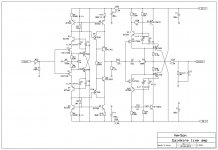
David Nelson (Comlinear) contacted Ed Dell and Ed gave him my phone number at work (LLNL). He was very interested in the line stage I published in 1980. He said they were just about to try to get a patent on amp like mine and would have to go back to the drawing board now.
Mine from 1970's and published in The Audio Ameature 1980 mag is shown like this ---> See Fig.5;
View attachment MarshPreamp.pdf
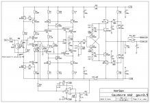
Comlinear added a diode and OP buffer. Like this--->

Later diamond I/O where added as well and better current-mirror.
Now we have this with higher OLG --->

But, Is the added I/O buffers and a current-mirror needed to behave as a CMA/CFB? No.
Today, I bread-boarded the original circuit using only the 4 transistors. (note the OLG is not high). I did not select the transistors at all. They are general purpose 2N2219A and 2N2905A.


Do a transistor match and you can add another zero to the THD at 10KHz.
Note- Tr driving 50 Ohm load and this is with lots of stray L and C from wiring. if we used a nice ground plane and smd we would be right at the max freq of the transistors.
When you change the Rf/Rg, it exhibits all the characteristic of a CMA..... Note that there was no name for this circuit characteristic when I developed it. I called it a symmetrical push-pull compound complimentary amplifier.
Some 40 years later, I made a headphone Amplifier using the same topology but added an OPS buffer... With selected and matched transistors < -120dB thd is achieved. Again, without very high OLG.
THx-RNMarsh
Last edited:
“This makes reasoning based upon cause and effect tricky, and it is necessary to analyze the system as a whole.” [emphasis added IH] by Karl Johan Åström and Richard M. Murray, Feedback Systems: An Introduction for Scientists and Engineers”
Which is of course why breaking the loop is such a powerful technique eg like Middleton, for analysis.
I’ve downloaded the pdf - will make interesting reading.thsnks for sharing.
Which is of course why breaking the loop is such a powerful technique eg like Middleton, for analysis.
I’ve downloaded the pdf - will make interesting reading.thsnks for sharing.
Hi Chris,
OK Ian, thanks for engaging.
Strange where these ideas come from......
David Nelson (Comlinear) contacted Ed Dell and Ed gave him my phone number at work (LLNL). He was very interested in the line stage I published in 1980. He said they were just about to try to get a patent on amp like mine and would have to go back to the drawing board now.
Mine from 1970's and published in The Audio Ameature 1980 mag is shown like this ---> See Fig.5;
Hi, somewhat off thread, I have a Spec An with a 16 bit A to D but have built a sine generator with distortion better than -130dB. I run the signal I want to measure through a passive notch filter with better than 60dB suppression of the fundamental. This is fine for solid state low output Z circuits, but I want to test tube circuits with Zout as high as 75k. I need a unity gain buffer whose non-linear input capacitance won't contribute to distortion when sourced from a high impedance. Do you know of any solutions you can point me to?
Strange where these ideas come from......
David Nelson (Comlinear) contacted Ed Dell and Ed gave him my phone number at work (LLNL). He was very interested in the line stage I published in 1980. He said they were just about to try to get a patent on amp like mine and would have to go back to the drawing board now.
Mine from 1970's and published in The Audio Ameature 1980 mag is shown like this ---> See Fig.5;
View attachment 720038
Comlinear added a diode and OP buffer. Like this--->
View attachment 720033
Later diamond I/O where added as well and better current-mirror.
Now we have this with higher OLG --->
View attachment 720039
But, Is the added I/O buffers and a current-mirror needed to behave as a CMA/CFB? No.
Today, I bread-boarded the original circuit using only the 4 transistors. (note the OLG is not high). I did not select the transistors at all. They are general purpose 2N2219A and 2N2905A.
View attachment 720042
View attachment 720043
View attachment 720041
Do a transistor match and you can add another zero to the THD at 10KHz.
Note- Tr driving 50 Ohm load and this is with lots of stray L and C from wiring. if we used a nice ground plane and smd we would be right at the max freq of the transistors.
When you change the Rf/Rg, it exhibits all the characteristic of a CMA..... Note that there was no name for this circuit characteristic when I developed it. I called it a symmetrical push-pull compound complimentary amplifier.
Some 40 years later, I made a headphone Amplifier using the same topology but added an OPS buffer... With selected and matched transistors < -120dB thd is achieved. Again, without very high OLG.
THx-RNMarsh
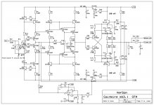
I designed and built three CFA line/phone preamps, GainWire (2013), Gainwire mk2 (2014 switchable CFA or non GNFB) and GainWire mk3 (2016 CFA, built balanced version).
Damir
Attachments
Hi, somewhat off thread, I have a Spec An with a 16 bit A to D but have built a sine generator with distortion better than -130dB. I run the signal I want to measure through a passive notch filter with better than 60dB suppression of the fundamental. This is fine for solid state low output Z circuits, but I want to test tube circuits with Zout as high as 75k. I need a unity gain buffer whose non-linear input capacitance won't contribute to distortion when sourced from a high impedance. Do you know of any solutions you can point me to?
The attached was designed many years ago to measure AC signals from the chemical reactions in the brain of some small rodents. It works on the principle of nulling feedback capacitances by tracking and maintaining the drain voltage to the gate and the gate voltage to the source.
The high impedance op amp prevents the variance in the drain/source current as would then cause voltage variations between the grid and source. I am not sure if I actually doubled the stacking of the FET's.
Attachments
Hi, somewhat off thread, I have a Spec An with a 16 bit A to D but have built a sine generator with distortion better than -130dB. I run the signal I want to measure through a passive notch filter with better than 60dB suppression of the fundamental. This is fine for solid state low output Z circuits, but I want to test tube circuits with Zout as high as 75k. I need a unity gain buffer whose non-linear input capacitance won't contribute to distortion when sourced from a high impedance. Do you know of any solutions you can point me to?
Yes, see Dadod, above. Or, my headphone amp design. With some additional selection/tweeking/trimming it got down to the analyser floor (AP 2722). The input devices are low C jFET's (HF/RF) but in this CMA configuration the C's effect cancel, anyway.
We had similar problem with a DIY project where a variable freq sine generator with harmonics I measured at -145dbv.... How to buffer/boost the signal without degrading the signal gen. It isnt easy but it can be done.
.jpg")
THx-RNMarsh
Last edited:
- Home
- Amplifiers
- Solid State
- Current Feedback Amplifiers, not only a semantic problem?