Early effect not included in the model?
Not exactly, the hybrid pi model without capacitance is unilateral i.e. there is not a literal internal resistor shunting the collector and emitter. Changing Vce changes the base width and hence beta. Hybrid pi is only a small signal approximation around a fixed bias point.
Perhaps I'm dense, and I'm not trying to be sarcastic here, but a metaphor does not serve to explain your point to me.
Then I guess I don't get your point. The DC performance of the CFA does not depend on the trans-conductance of the input devices this is not a particularly useful or interesting point and speaks not at all to either side of the argument.
Yeah , just like the last CFA big thread. Either argue the semantics into infinity ...
or design 10 CFA's and 10 VFA's to see whether it even matters. (I did that 2 years
ago).
All 20 "slewmaster' CFA/VFA's were nearly identical sounding and rock solid.
Some designs favored some systems (loudspeakers) , but only in very minor aspects.
So , off we go again "nickle/diming" the theory to death and trying to create
something out of nothing (again).)
I must thank the last group of "nickle /dimers" for giving me a freaking headache
which triggered me to design a whole bunch of amps.
2 cents ain't worth squat.
Ain't got time for this 'old tech' anymore (class G or D + SMPS = 21'st century).
Edit- this thread is like "blowtorch 2".
OS
OS
Welcome back Ostripper- trust you enjoyed your travels!
Indeed, the argument over semantics goes on. the EDN and Audio Xpress wells have now also been poisoned.
My CFA and VFA amps also all sound rock solid.
Sorry, I wont be joining you down the class D/H +SMPS route. That's sacrilege man.
Am not with the PC that has the sim right now, but would Ic(Q6) be the difference between the red and green?
Jan
In the small signal regime the difference in the collector currents of Q6 and Q12 is the net current out of the current mirrors. If you open up the models and make VA and beta huge the curves lie on top of each other, I don't see the reluctance to do this and realize that the low frequency behavior is simply process/device limitations not fundamental to the topology.
My point is related to the audio frequency performance of the CFA. If you want me to add a capacitor to my sim because you believe it is needed to reflect audio frequency operation, please confirm its value and location (Q5 collector?) and I will repeat to see if anything changes.
I do believe that post 1028 adds to the argument, as it clarifies what is happening with the input transistor.
We have different attitudes towards the "never current feedback" types. At this point, you blow them off. I am trying to demonstrate the consequences of their arguments. In this case, that the function of the CFA input transistor (I believe) is subject to significant variations in vce as well as those of vbe; it's not just a transconductor. The "vf" paradigm is becoming more complicated as we delve into it. The "cf" paradigm, which some emphatically reject, is mostly indifferent to the internal details of transistor operation once it is acknowledged that ic and ie are almost identical. It is a simpler and perfectly adequate explanation of what is happening.
If I'm allowed an exaggeration here, the voltage feedback view is Ptolemaic in comparison to the Copernican current feedback paradigm.
My understanding is that there is not even agreement about what happens at DC, never mind at HF where traditionally CFA's were applied (ok, nowadays there are very fast VFA's, but we are talking 'classic' topologies here).
I agree, the existing CFA explanation is by far the easiest to grasp (Occam's razor). I mentioned a few posts back that one need not invoke semiconductor fundamentals - a simplified amplifier model explains it fully, as is the case with the VFA.
I agree, the existing CFA explanation is by far the easiest to grasp (Occam's razor). I mentioned a few posts back that one need not invoke semiconductor fundamentals - a simplified amplifier model explains it fully, as is the case with the VFA.
My point is related to the audio frequency performance of the CFA. If you want me to add a capacitor to my sim because you believe it is needed to reflect audio frequency operation,
It's known as the compensation capacitor, if the amplifier oscillates it's not useful for anything. Using slow devices with large parasitic capacitances does not oscillate by sheer chance not design.
It's known as the compensation capacitor, if the amplifier oscillates it's not useful for anything. Using slow devices with large parasitic capacitances does not oscillate by sheer chance not design.
Fully agree.
The question I asked to myself today :
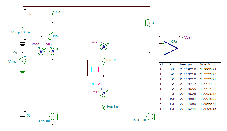
can we still speak of a CFA when the impedance the feedback network is hugely smaller than the impedance of the inverting output ?
Amperes being free in simulation, it's easy to see what happens when resistors Rf and Rg, made equal here, vary from 1 mΩ ot 10 kΩ. Result : the current of the at the inverting input changes of 0.3% only.
The output impedance of T1 at 1 mA is about 25 Ohm.
The arrows indicate the phase of the currents.
Attachments
Last edited:
Chris,
Thanks for having taken the trouble to come with this calculation.
Hans
Hans,
Here is an extension of the derivation of the importance of ro in the CFA input transistors. Referencing the schematic in Post 1160, I developed the ratio of the current due to transconductance to that of the Early Effect. If we assume that the transistors implementing Z(s) are similar to the input transistors responsible for ro, we find that at frequencies below those at which Z is noticeably capacitive, the ratio is approximately 2 + Rf/Rg. That's almost exactly the simulation result.
As is often the case, I found MathCad's equation manipulation capabilities to be very useful.
Attachments
For CPaul
I spent (hopefully not wasted) my time this morning making a little sim. This is the simplified CFA circuit very similar to the one on the AD844 datasheet, made with BC550 and BC560 transistors (because I just moved stuff around on something else I was working on). This does not really matter.
Scott, thank you for the simulation file. From my point of view, you certainly haven't wasted your time. The Wilson current sources make the resistive portion of T(s) truly enormous!
I know that you are not fond of looking at things this way, but here goes.
I modified your file for time domain operation at 1kHz (attached, adding the Bob Cordell file it requires. Its .txt extension must be modified to .inc). The approximate transconductance of Q6 is 1mA / 26mV, whose reciprocal is 38 ohms. But the measured ratio of 1kHz AC signals vbe6 / ic6 is 432 ohms!
The reason for this is explained in the attached derivation where it is seen that the ratio of the transconductance to Early currents is 1 + ( 1 + Rf / Rg ) · ro / (Rf + Z). Here, Z is the ground-referenced impedance at the junction of Q14 and Q16, and ro is the small signal Hybrid model Early resistor between Q6’s emitter and collector. For this simulation, Rf is R1 and Rg is infinity.
At 1kHz in your sim, Z >> ro and so the current ratio is only a little greater than unity. Because the currents subtract, we have the rather large 432 ohm vbe6 / ic6.
The point of all of this is solely to point out that describing the CFA as having only voltage-driven tranconductance feedback is clearly flawed. Nothing more is intended from this demonstration.
Attachments
The point of all of this is solely to point out that describing the CFA as having only voltage-driven tranconductance feedback is clearly flawed. Nothing more is intended from this demonstration.
The voltage across a diamond input is inseparable from the current out (at high frequencies where it matters) this is cause and effect semantics. I had a thought all these examples as voltage followers add the confounder of common mode effects it might be better to talk around inverting configurations.
Here's the math you requested.
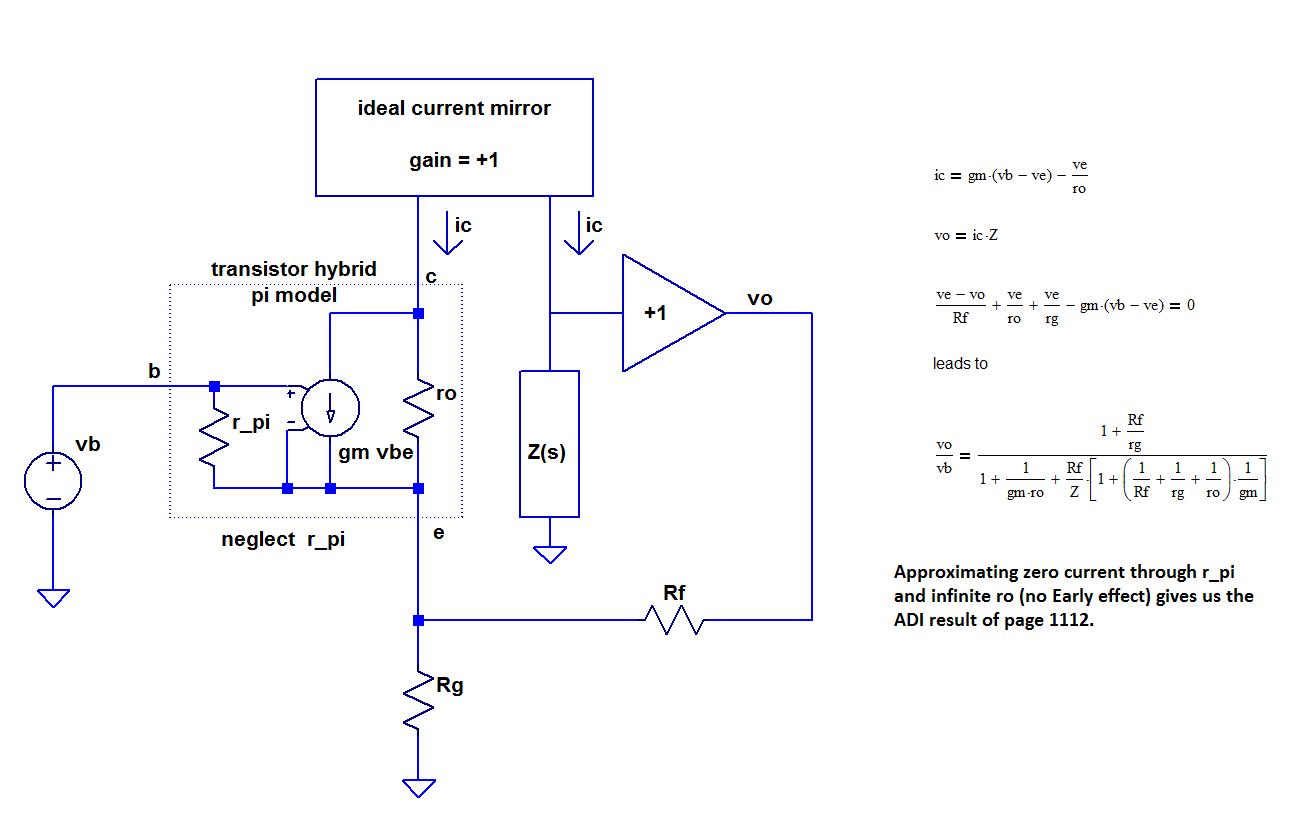
In an earlier post I suggested that the nature of a CFA or VFA changes as a function of current reversal in the feedback resistor Rf. To support this belief Figure 1 has been reproduced in a form such as yours. In this example your Z(s) has been replaced by a 10K Ohm resistor (hence DC only). The unit of current from the current mirrors set to 1mA as thereupon yielding a 10 Volt DC output.
If we consider the Hfe of the transistor hybrid at 100, the emitter current becomes 1.01 mA. The output resistor Rg becomes.
Rg = 10Volts / 1.01mA or 9.9K Ohms.
Although Rf is shown as 10K ohms it isn't relevant. Under circumstances that cause 0 volts across the feedback resistor, the Rf value can be anything from zero to infinity. In other words, feedback can't be applied as either voltage or current as neither can cause a current flow to affect the outcome.
Current reversal occurs by changing Rg, perhaps from 9.8K to 10.0 K ohms. This leads to the question as to what a device was before and after the current reversal. Can a device remain a current or voltage feedback amplifier through a null condition that it can't be either? This also brings into question if a CFA is a feedforward device if the emitter is greater than the Vout and a feedback device if the emitter is less than the Vout.
It can be viewed that Rg in relation to Z(s) is a determining factor to support current reversal. This can't happen if Rg doesn't exist, as all current must pass through Rf in the same direction as passes through Z(s).
If we now examine CFA's and VFA's in a similar way in Fig. 2, it can be seen that the zero current (zero feedback) crossover occurs in a VFA for Rg values of 1Meg Ohm (note that Rf value of 10K Ohm is also irrelevant). It can be seen that at the zero feedback point a VFA doesn't have a low value resistance to work against. This is to suggest that in the absence of feedback a VFA has Hfe less drive to cause an output change than a CFA in absence of feedback.
Attachments
The voltage across a diamond input is inseparable from the current out (at high frequencies where it matters) this is cause and effect semantics. I had a thought all these examples as voltage followers add the confounder of common mode effects it might be better to talk around inverting configurations.
I fail to see how semantics enters into this. And your expressed criticisms, for me at least, are too vague to examine in detail.
At audio frequencies, ic is a function of both vbe and vce, as even Ebers-Moll makes clear. The single transistor simulation of Post 1028 also demonstrates this. I have little doubt that a simulation of the transistor you used in your sim would show the same.
The sim model you sent me shows that ic/vbe is quite different from the transconductance IC q / (k T). Application of the small signal Hybrid Pi model explains why. I do not understand your objection to this demonstration.
In an earlier post I suggested that the nature of a CFA or VFA changes as a function of current reversal in the feedback resistor Rf. To support this belief Figure 1 has been reproduced in a form such as yours. In this example your Z(s) has been replaced by a 10K Ohm resistor (hence DC only). The unit of current from the current mirrors set to 1mA as thereupon yielding a 10 Volt DC output.
If we consider the Hfe of the transistor hybrid at 100, the emitter current becomes 1.01 mA. The output resistor Rg becomes.
Rg = 10Volts / 1.01mA or 9.9K Ohms.
Although Rf is shown as 10K ohms it isn't relevant. Under circumstances that cause 0 volts across the feedback resistor, the Rf value can be anything from zero to infinity. In other words, feedback can't be applied as either voltage or current as neither can cause a current flow to affect the outcome.
Current reversal occurs by changing Rg, perhaps from 9.8K to 10.0 K ohms. This leads to the question as to what a device was before and after the current reversal. Can a device remain a current or voltage feedback amplifier through a null condition that it can't be either? This also brings into question if a CFA is a feedforward device if the emitter is greater than the Vout and a feedback device if the emitter is less than the Vout.
It can be viewed that Rg in relation to Z(s) is a determining factor to support current reversal. This can't happen if Rg doesn't exist, as all current must pass through Rf in the same direction as passes through Z(s).
If we now examine CFA's and VFA's in a similar way in Fig. 2, it can be seen that the zero current (zero feedback) crossover occurs in a VFA for Rg values of 1Meg Ohm (note that Rf value of 10K Ohm is also irrelevant). It can be seen that at the zero feedback point a VFA doesn't have a low value resistance to work against. This is to suggest that in the absence of feedback a VFA has Hfe less drive to cause an output change than a CFA in absence of feedback.
I'm quite familiar with this phenomenon. forr and I discussed it in the circuit of post 789. In Post 813, he acknowledged that for some value of Rg, the relative directions of the current flows switch. So of course, there is a null point.
Both circuits in Figure 2 look to me to have a CFA topology.
At audio frequencies, ic is a function of both vbe and vce, as even Ebers-Moll makes clear. The single transistor simulation of Post 1028 also demonstrates this. I have little doubt that a simulation of the transistor you used in your sim would show the same.
Cascode the input devices and the current mirror outputs with JFET's now there is no change in Vce and the plot extends to virtually DC.
Yes, that would minimize the influence of vce. But few if any commercial CFAs are built that way.
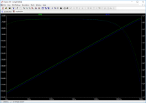
That matters to theoretical analysis? It works BTW see below.
Attachments
I'm quite familiar with this phenomenon. forr and I discussed it in the circuit of post 789. In Post 813, he acknowledged that for some value of Rg, the relative directions of the current flows switch. So of course, there is a null point.
Both circuits in Figure 2 look to me to have a CFA topology.
I looked up the posts, thanks CPaul... My argument is not the same, rather there is no intention that my circuit values are intended to prove a device to be one type or another, rather that the point of current reversal is the determinant factor as the pivotal point of a device being characterized as a current or voltage feedback device. I recognize that most implementations are far from this point. My intention was to suggest that once current direction has been established the designation of a device doesn't change to any extent as regardless how far from the pivotal point a device becomes.
It is considered that if a device has a voltage output greater than the non-inverting terminal it is a voltage feedback device. If the device has a voltage output less than the non-inverting terminal it is a current feedback device.
For normal internal resistance values of CFA's at the Tz node as perhaps 3M Ohm in an AD844, the Rg value must be typically greater than 3M Ohm for it to be characterized as a current feedback device. In the case of a VFA with the same 3M Ohm Tz node resistance and perhaps 100x Hfe gain the Rg value must be typically 300M Ohm to be characterized as a CFA. For this reason it is difficult to imagine a VFA as ever being considered a CFA, even in absence of an Rg resistor.
In situations whereupon a CFA is configured as a buffer having no Rg resistor, the infinite value of Rg exceeds the 3M Ohm internal Tz value, hence all CFA's connected as buffers can be considered current feedback devices.
The bottom circuit in Figure 2 was simply intended to identify any device whereupon current has been magnified. The value of Rg was calculated to reflect a zero feedback condition. This identifies the drastic reduction of current drive available to R1, as demonstrating the current drive advantages of a CFA device with 1:1 current mirrors under zero feedback conditions.
That matters to theoretical analysis? It works BTW see below.
The subject I am addressing is classical CFA's. Because that's what our "ne'er current-feedbackers" are claiming are purely voltage-transconductance-driven. Which, as I have demonstrated, they clearly aren't.
I'm not addressing CFAs that could be redesigned to avoid a characteristic that doesn't appear to be a problem in the first place. If you want to go there, fine, but that's something whose relevance to this dispute that I don't see and that I have no great interest in pursuing.
- Home
- Amplifiers
- Solid State
- Current Feedback Amplifiers, not only a semantic problem?