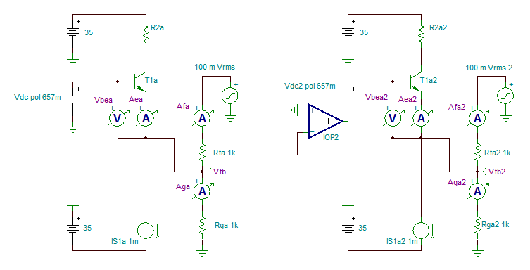
A first sight, the ideal input stage I suggested leads to a theorical perfect CFA (right circuit in the image below).
Looking carefullly, we see that this perfection is obtained by a perfect voltage control between the non-inverting and the inverting input by the ideal op-amp. The low impedance of the inverting input is not only preserved but is ideally null. So the ideal CFA operates like a VFA on voltage difference between its two inputs. This means the input stage is a differential input stage.
What appears with a realistic CFA is that it suffers from imperfection (well, far from dramatic) but the whole principle of differential input stays valid.
In fact, the input stage of a CFA, below on the left with a simple transistor, combines two functions at once :
1. sensing the voltage between its base and it emitter
2. delivering current to the feedback network
To me, it is the cause of the difference of the interpretations .
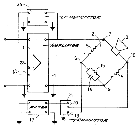
Looking at a single amplifying device as a differential device is not new. I discovered the analogy with Tadeusz Korn who explicitely used it like that in his Servo-Sound motional feedback amplifier, US patent 3 647 969, second image below.
Looking carefullly, we see that this perfection is obtained by a perfect voltage control between the non-inverting and the inverting input by the ideal op-amp. The low impedance of the inverting input is not only preserved but is ideally null. So the ideal CFA operates like a VFA on voltage difference between its two inputs. This means the input stage is a differential input stage.
What appears with a realistic CFA is that it suffers from imperfection (well, far from dramatic) but the whole principle of differential input stays valid.
In fact, the input stage of a CFA, below on the left with a simple transistor, combines two functions at once :
1. sensing the voltage between its base and it emitter
2. delivering current to the feedback network
To me, it is the cause of the difference of the interpretations .
Looking at a single amplifying device as a differential device is not new. I discovered the analogy with Tadeusz Korn who explicitely used it like that in his Servo-Sound motional feedback amplifier, US patent 3 647 969, second image below.
Attachments
A first sight, the ideal input stage I suggested leads to a theorical perfect CFA (right circuit in the image below).
It appears that we are not having a conversation. Instead, you are simply making one presentation after another and ignoring what I am saying.
Frankly, I don't see the point of continuing to engage with you.
Does everyone understand how CFB works now? can we move on?
THx-RNMarsh
I know perfectly well how a CFA works and have known it for years without "help" from you.
As I said you are just confusing things.
BTW: I think you should keep the DA discussion to the blowhard thread where it belongs, sorry the Blowtorch thread.
For your information I have designed amplifiers using both CFA, VFA with LTP and VFA using H-Bridge IPS, as well as open loop amplifiers with a transresistance ips (with a buffer). And Class D amps.
I did put up some of my designs on a DIY audio engineering forum that regrettably were closed down some years ago.
Let us move on with the technical discussion, see next post.
")
Cheers
In my opinion the Burr-Brown/Ti sboa047 app. note explains very well the difference between CFA and VFA.
Please read the first 8 pages. The firs pages is about CFA and page 8 is about a CFA converted to a VFA.
The opamps that is discussed is the OPA666 wich is a CFA and the OPA622 wich can be used as both a CFA and a VFA by adding a buffer in the feedback path.
In the OPA622 one have access to all the different "building blocks".
In my opinion the OPA622 is a good example when the difference between CFA and VFA is discussed.
Cheers
Attachments
In the OPA622 one have access to all the different "building blocks".
In my opinion the OPA622 is a good example when the difference between CFA and VFA is discussed.
Cheers
Yes, but THD and noise are nothing to write home about.
It appears that we are not having a conversation. Instead, you are simply making one presentation after another and ignoring what I am saying.
Frankly, I don't see the point of continuing to engage with you.
I don't see this as necessarily complex. Operational type VFA's and CFA's seem can be evaluated simply on the basis of the resistance at the Tz node and two resistors that make up the feedback path. One resistor from the output to the inverting terminal and the other from the inverting terminal to ground. The identification of an amplifier being of a voltage or current type seems nothing more than a function of the direction of current flow in the feedback resistor, mostly when Av is around 0dB. This is to suggest that VFA's and CFA's can be either type as pivotal around that point. The conclusion is also that neither a VFA or CFA can be a VFA in the absence of a resistor to ground for reasons that the current can't then be reversed in the feedback resistor.
Yes, but THD and noise are nothing to write home about.
That's right but that was not the point.
Optimizing each configuration (VFA/CFA) for an actual application rather than an intellectual exercise requires access to internal pins. At these speeds this is not practical or optimum.
most definitely.
If we limit the use to audio apps only ... Noise is probably not as much of an issue any more -- except in legacy phono and in microphone preamp apps. For the DIY'er, like myself, it is apps for filters, line levels and power apps.
THx-RNMarsh
Last edited:
For your information I have designed amplifiers using both CFA, VFA with LTP and VFA using H-Bridge IPS, as well as open loop amplifiers with a transresistance ips (with a buffer). And Class D amps.
Cheers
Did you get any patents? Do anything original? What was it?
THx-RNMarsh
I don't see this as necessarily complex.
You do know that the comment you quoted was not directed at you, right?
Operational type VFA's and CFA's seem can be evaluated simply on the basis of the resistance at the Tz node and two resistors that make up the feedback path. One resistor from the output to the inverting terminal and the other from the inverting terminal to ground. The identification of an amplifier being of a voltage or current type seems nothing more than a function of the direction of current flow in the feedback resistor, mostly when Av is around 0dB. This is to suggest that VFA's and CFA's can be either type as pivotal around that point. The conclusion is also that neither a VFA or CFA can be a VFA in the absence of a resistor to ground for reasons that the current can't then be reversed in the feedback resistor.
It is interesting that a CFA with a resistor connecting the inverting input and the output but none connecting the inverting input and ground actually exhibits positive feedback when operating closed loop, and even more interesting that it can be recommended for use in this manner.
However, even in this situation, the "slew rate enhancement on demand" current is available from the CFA output, but not from the "classical" VFA output. This is an important functional distinction between the two that remains even for 0dB closed loop gain configurations. Of course, modern "enhanced" VFAs don't necessarily suffer from this limitation.
Last edited:
I think you meant "In a VFA the input stage output current comes from the tail current".Ian, I beg to differ. One large difference is that in a CFA the input stage output current comes from the -inp emitter, i.e. from the feedback network.
In a CFA the input stage output current comes from the tail current.
So, in addition to the difference in impedance level, there is a conceptual difference as well. A VFA is not 'just' a CFA with lower Zin at -inp!
Jan
Like LazyCat (next post 1118) and many others you are thinking of a VFA with the traditional LTP diff amp input stage. But a VFA does not have to be that type of IPS. A VFA can have the current on demand input stage of a CFA where there's no "tail-current".
Now try my thought experiment with a VFA current-on-demand input stage. (Post 1115)
Last edited:
I think you meant "In a VFA the input stage output current comes from the tail current".
Like LazyCat (next post 1118) and many others you are thinking of a VFA with the traditional LTP diff amp input stage. But a VFA does not have to be that type of IPS. A VFA can have the current on demand input stage of a CFA where there's no "tail-current".
Now try my thought experiment with a VFA current-on-demand input stage. (Post 1115)
Yes I meant VFA, apologies.
Yes, you can construct what I think is often called here an H-bridge, basically two CFA's interconnected through each other's Rf.
But the discussion I was reacting to was a CFA or a CFA with a buffer/emitter follower on the inv input. The latter turns it into an LTP and the stage output current no longer comes from the inv input current but from the tail current.
And that not only changes the impedance level but also the topology.
Then you have two high impedance inputs and still the advantages of a CFA. But note that the interconnecting Rf still provides the current that ultimately forms the stage output (collector) current. So considering that, it would make sense to still call it a CFA, maybe a balanced or push-pull CFA. You can call it a current-on-demand VFA but that seems less logical to me since it is based on a specific topology of a CFA. Anyway, we were not yet at the stage of naming all kinds of bastards. We still have to agree on the original, simple different topologies ;-)
Jan
It is interesting that a CFA with a resistor connecting the inverting input and the output but none connecting the inverting input and ground actually exhibits positive feedback when operating closed loop, and even more interesting that it can be recommended for use in this manner.
It's known as a voltage follower, what am I missing? There is no positive feedback.
Anyway, we were not yet at the stage of naming all kinds of bastards. We still have to agree on the original, simple different topologies ;-)
Jan
Amen. Preserve and rescue us all from arguments based on the names we assign to circuits when our group of unherdable cats can't even seem to agree on how they function!
It's known as a voltage follower, what am I missing? There is no positive feedback.
Input and output stage currents both flow out of (or into) a substantial Rg in the same direction, in opposition, and we have negative feedback.
With no Rg, the very small output and input stage currents must flow in the same direction due to conservation of charge at their junction.
Input and output stage currents both flow out of (or into) a substantial Rg in the same direction, in opposition, and we have negative feedback.
With no Rg, the very small output and input stage currents must flow in the same direction due to conservation of charge at their junction.
Not at substantial frequency where it matters. This ro and beta errors stuff is really irrelevant to anything.

Not at substantial frequency where it matters.
Perhaps. It was a response to a rather impractical distinction in the first place.
This ro and beta errors stuff is really irrelevant to anything.
Regarding ro at audio frequencies, consider that the large loop gain significantly reduces the AC vbe voltage, and therefore the AC current arriving through the voltage-controlled transconductance.
But the same large loop gain does not affect the AC vce; the Early effect is now a significant contributor to collector current in comparison to that of the vbe transconductance. See Post 1028 for a simulation which illustrates this.
You should be careful about hitting your head repeatedly - you could hurt yourself!
Could you please take the trouble to add these imperfections to the generally used transfer function of the CFA.Regarding ro at audio frequencies, consider that the large loop gain significantly reduces the AC vbe voltage, and therefore the AC current arriving through the voltage-controlled transconductance.
But the same large loop gain does not affect the AC vce; the Early effect is now a significant contributor to collector current in comparison to that of the vbe transconductance. See Post 1028 for a simulation which illustrates this.
You should be careful about hitting your head repeatedly - you could hurt yourself!
That will tell to what degree your comments are relevant and whether anybody is hitting his head.
No sims, just plain mathematics.
Hans
Apply Occam's Razor...it would make sense to still call it a CFA, maybe a balanced or push-pull CFA. You can call it a current-on-demand VFA but that seems less logical to me since it is based on a specific topology of a CFA. Anyway, we were not yet at the stage of naming all kinds of bastards. We still have to agree on the original, simple different topologies ;-)
Jan
The VFA name existed before the CFA name was coined. Using "balanced or push-pull CFA" for the new VFA is adding unnecessary complexity.the simplest solution tends to be the correct one.
To distinguish between the old VFA and the new I have seen "traditional VFA" and and "classical VFA" (opa622.pdf) and new as "modern VFA" by Ramus.and "exteded VFA" by Henn (sboa47.pdf). There are likely more.
My point of the thought experiment was to establish that there is really no change over from one topology to the other ... so they must be the same topology as hard as that is for some to accept. This is possible because the internal workings of feedback is voltage across the base-emitter and that doesn't (cannot) change when the inverting input buffer is morphed down to a piece of wire. ..
Ian
- Home
- Amplifiers
- Solid State
- Current Feedback Amplifiers, not only a semantic problem?