Geoff's JLH PCBs
I've just finished a prototype of a JLH using Geoff's PCB layouts (thanks, Geoff!). This is a temporary setup while I decide on final packaging.
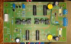
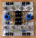
Here's a populated board. Notice it's single-sided, and only one wire link is needed. This is an easy board to stuff, I'd recommend this project to beginners except for the heatsinking and power supply requirements make it a fairly involved project.
I've just finished a prototype of a JLH using Geoff's PCB layouts (thanks, Geoff!). This is a temporary setup while I decide on final packaging.
Here's a populated board. Notice it's single-sided, and only one wire link is needed. This is an easy board to stuff, I'd recommend this project to beginners except for the heatsinking and power supply requirements make it a fairly involved project.
Attachments
Re: Re: Geoff's JLH PCBs
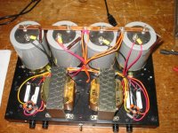
The power supply is almost 100% recycled parts. The transformers came from a pair of Advent Powered Loudspeakers (that are currently UnPowered); To get the proper voltage, I wired their primaries in series and their secondaries in parallel via the 10W current sharing resistors. I was originally going to add a capacitance multiplier but with the big capacitors I have Geoff suggested it was good enough without. Also, I didn't want to suffer the voltage drop and lower the rail voltages any further.
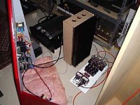
If I use this for the final arrangement, and it goes somewhere other than my lab, I'll have to hide it away (I've been told).
I think I might just keep it in the lab, though...
The power supply is almost 100% recycled parts. The transformers came from a pair of Advent Powered Loudspeakers (that are currently UnPowered); To get the proper voltage, I wired their primaries in series and their secondaries in parallel via the 10W current sharing resistors. I was originally going to add a capacitance multiplier but with the big capacitors I have Geoff suggested it was good enough without. Also, I didn't want to suffer the voltage drop and lower the rail voltages any further.
If I use this for the final arrangement, and it goes somewhere other than my lab, I'll have to hide it away (I've been told).
I think I might just keep it in the lab, though...
Attachments

J-amp 2003..
My 2 J-amp-2003's are still in use on a daily basis.
I've not even measured the actual DC-offset for the last year.
Probably a check might be nice.")
They still have an audible ''thumb'' at power on. but i don't care.
Soundwise I'm still impressed with the fine combination of the J-amp 2003 and my JMLab Symbol II's.
My 2 J-amp-2003's are still in use on a daily basis.
I've not even measured the actual DC-offset for the last year.
Probably a check might be nice.
They still have an audible ''thumb'' at power on. but i don't care.
Soundwise I'm still impressed with the fine combination of the J-amp 2003 and my JMLab Symbol II's.
Re: Differential (Xed) JLH
hi
This topology interests me
Have you build this amplifier since?
thx
EUVL said:Any comments ?
Patrick
hi
This topology interests me
Have you build this amplifier since?
thx
Attachments
> Have you build this amplifier since?
Yes, using 8x MJ21194 per channel. +/- 15V, Total bias 5.6A. Gives you roughly 40W at 4 Ohm & 8 Ohm. Peaks at 6 Ohm.
Photo too large to post here. No housing yet. Just on heatsinks.
Try it for yourself. It won't take too much effort. Use a lab supply to see if you like it first before the big investment.
Thank you for your interest,
Patrick
Just managed to get it down to below 100kB.
Picture quality is horrible, but not much I can do.
This is one channel which is bolted onto a heatsink of 0.2K/W.
Circuit as posted except for the output transistors, as already mentioned.
Everything matched.
Patrick
Picture quality is horrible, but not much I can do.
This is one channel which is bolted onto a heatsink of 0.2K/W.
Circuit as posted except for the output transistors, as already mentioned.
Everything matched.
Patrick
Attachments
EUVL said:> Have you build this amplifier since?
Yes, using 8x MJ21194 per channel. +/- 15V, Total bias 5.6A. Gives you roughly 40W at 4 Ohm & 8 Ohm. Peaks at 6 Ohm.
Photo too large to post here. No housing yet. Just on heatsinks.
Try it for yourself. It won't take too much effort. Use a lab supply to see if you like it first before the big investment.
Thank you for your interest,
Patrick
EUVL said:Just managed to get it down to below 100kB.
Picture quality is horrible, but not much I can do.
This is one channel which is bolted onto a heatsink of 0.2K/W.
Circuit as posted except for the output transistors, as already mentioned.
Everything matched.
Patrick
Thanks for your answer
it is possible to use BC560, MJL driver and MJL 3281 ?
> it is possible to use BC560, MJL driver and MJL 3281 ?
Have not tried, so better not comment. But please have a look through Geoff's JLH website for alternative transistors.
You can get the Toshiba transistors at Fibra Brandt (near the French border), and MJ15003 from Reichelt.de (On Semi, 2.35 Euros each). Alternatively, order samples from the On Semi website. Don't order Japanese transistors from Reichelt. They are anything but original Toshiba / Hitachi, except for some Power FETs.
Patrick
Re: Re: Re: Geoff's JLH PCBs
how big are those caps anyway? they look huge.
paulb said:I was originally going to add a capacitance multiplier but with the big capacitors I have Geoff suggested it was good enough without. Also, I didn't want to suffer the voltage drop and lower the rail voltages any further.
If I use this for the final arrangement, and it goes somewhere other than my lab, I'll have to hide it away (I've been told).
I think I might just keep it in the lab, though...
how big are those caps anyway? they look huge.
Re: Re: Re: Re: Geoff's JLH PCBs
68000 uF (68 mF), 63V.bikehorn said:
how big are those caps anyway? they look huge.
Re: Geoff's JLH PCBs
Hi Paul,
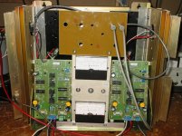
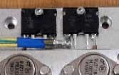
do both driver transistors get warm? those are 10degC/W heatsinks right?
What part numbers are they?
thanks
Chris
paulb said:I've just finished a prototype of a JLH using Geoff's PCB layouts (thanks, Geoff!).
Hi Paul,
do both driver transistors get warm? those are 10degC/W heatsinks right?
What part numbers are they?
thanks
Chris
Re: Re: Geoff's JLH PCBs
I got the heatsinks surplus from a place in Silicon Valley, don't know the part#. Digi-Key sells something that will work. They are oversized, something smaller would work.bremen nacht said:
Hi Paul,
do both driver transistors get warm? those are 10degC/W heatsinks right?
What part numbers are they?
thanks
Chris
- Home
- Amplifiers
- Solid State
- JLH 10 Watt class A amplifier