a21 vs ljhood class a
thanks for the response to my question rmvgs.I have the circuit
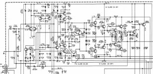
diagram of the original a21 sugden from hifinews cir.1970 one day I will get around to building it ,and comparing to my hart electronics 1996(published in electronics world) 10w class a amp.If one looks at the circiut diagram the sugden is much more complicated and uses a kind of push-pull drive to npn output
stage.
thanks for the response to my question rmvgs.I have the circuit
diagram of the original a21 sugden from hifinews cir.1970 one day I will get around to building it ,and comparing to my hart electronics 1996(published in electronics world) 10w class a amp.If one looks at the circiut diagram the sugden is much more complicated and uses a kind of push-pull drive to npn output
stage.
not that more complicated
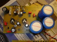
P Robertson, I wouldn't say the Sugden is that more complicated than the JLH. In essence I think the Sugden has also 3 gain stages if the output is seen as a Darlington-pair. For the jlh-2003, which has some extra transistors for regulating bias and offset, the differences in components-count vis-a-vis the sugden is again smaller. The Sugden is more efficient and can put out 2 times the idle-current, where the jlh has a figure of around 1,3-1,5. In other words: for 20 Watts RMS you need 1,1 Amps for the Sugden and around 1,7-2,0 Amps for the jlh (depending on the version you choose). Of course, both amps are inefficient as you compare it to for example a Hiraga which can still work in class-AB when choosing a small idle current. Another point: the Sugden article is written after the original jlh-article (1970 and 1969) and James Sugden explicitly refers to the article of John Linsley-Hood. The picture shows you a hard-wired version with all components (excluding power transformer and bridge) for one channel Sugden.
P Robertson, I wouldn't say the Sugden is that more complicated than the JLH. In essence I think the Sugden has also 3 gain stages if the output is seen as a Darlington-pair. For the jlh-2003, which has some extra transistors for regulating bias and offset, the differences in components-count vis-a-vis the sugden is again smaller. The Sugden is more efficient and can put out 2 times the idle-current, where the jlh has a figure of around 1,3-1,5. In other words: for 20 Watts RMS you need 1,1 Amps for the Sugden and around 1,7-2,0 Amps for the jlh (depending on the version you choose). Of course, both amps are inefficient as you compare it to for example a Hiraga which can still work in class-AB when choosing a small idle current. Another point: the Sugden article is written after the original jlh-article (1970 and 1969) and James Sugden explicitly refers to the article of John Linsley-Hood. The picture shows you a hard-wired version with all components (excluding power transformer and bridge) for one channel Sugden.
Attachments
CCS on LED/transistor? Why not?
Dear Geoff,
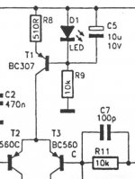
maybe I missed somth, but why not to use simplified CCS based on one transistor and one LED?
This is much simplier way compared to 2 transistors and 2 pots?
It is no easy to bias such thing...
Even Marantz using leds/diodes in power amp schematics for that purpose...
Dear Geoff,
maybe I missed somth, but why not to use simplified CCS based on one transistor and one LED?
This is much simplier way compared to 2 transistors and 2 pots?
It is no easy to bias such thing...
Even Marantz using leds/diodes in power amp schematics for that purpose...
Attachments
Re: CCS on LED/transistor? Why not?
Hi kesrmk
In terms of component count, there is not much difference between the two transistor ccs and the LED/transistor version. I chose the former for several reasons.
In the dc offset ccs (Q5/Q6), the Vbe variation with temperature of Q5 alters the ccs current in such a way as to negate some of the output dc offset change due to temperature variations in Q3 and Q4. Thus there is less output dc offset drift with changing ambient temperatures and during warm up.
Also, JLH himself used this ccs arrangement in the input stage of another of his power amp designs and so I was keeping with something that the original designer had used.
The advantage with using the two transistor ccs to set the output stage quiescent current is that the reference voltage is the Vbe of Q7 (~0.6V). This is less than that for an LED ccs so the peak output voltage swing, for a given rail voltage, will be higher thus giving a (slightly) greater efficiency.
Geoff
kesrmk said:maybe I missed somth, but why not to use simplified CCS based on one transistor and one LED?
Hi kesrmk
In terms of component count, there is not much difference between the two transistor ccs and the LED/transistor version. I chose the former for several reasons.
In the dc offset ccs (Q5/Q6), the Vbe variation with temperature of Q5 alters the ccs current in such a way as to negate some of the output dc offset change due to temperature variations in Q3 and Q4. Thus there is less output dc offset drift with changing ambient temperatures and during warm up.
Also, JLH himself used this ccs arrangement in the input stage of another of his power amp designs and so I was keeping with something that the original designer had used.
The advantage with using the two transistor ccs to set the output stage quiescent current is that the reference voltage is the Vbe of Q7 (~0.6V). This is less than that for an LED ccs so the peak output voltage swing, for a given rail voltage, will be higher thus giving a (slightly) greater efficiency.
Geoff
Hi
I'm a newbie of JLH.
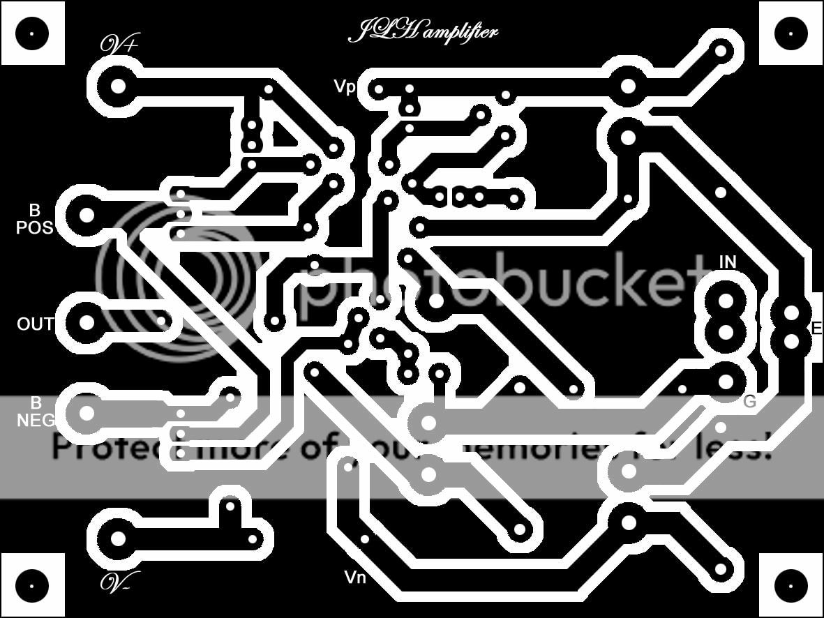
I'd like to try to bulld one of my own, so I spend a little time to draw a driver for it.....
The Q1/Q2 and R10 will mount on heatsink, using hard wire to connect the driver.
please kindly check if there's anything goes wrong or oscilate.
If all of you think it is OK, I'll post the solder PCB.
cheers
Coffin
I'm a newbie of JLH.
I'd like to try to bulld one of my own, so I spend a little time to draw a driver for it.....
The Q1/Q2 and R10 will mount on heatsink, using hard wire to connect the driver.
please kindly check if there's anything goes wrong or oscilate.
If all of you think it is OK, I'll post the solder PCB.
cheers
Coffin
Hi
Please check this schematic, from JLH update:
cheers
coffin
Please check this schematic, from JLH update:
An externally hosted image should be here but it was not working when we last tested it.
cheers
coffin
Not that anything is wrong but a suggestion...
Looking at the JLH schematic u have 3 current drawing branches viz the 2 ccs and the o/ps
At the filter capacitor, make a star point and take two separate tracks to the 2 ccs. It will be better since both the currents will seperate out. Anyhow u have lot of real estate that will go waste. Do the same for V- and ground.
Gajanan Phadte


the jlh pwramp for audiophiles ,class-a has demonstrated the fine qualities of sonic
accuracy and detail, class-a is evolving thats for sure, we take off where this fine class-a
has left off, purity,freq,distortion,speed, etc.... all are being improved by our class-a experts
what an example of class-a superior natural sonics
regards
accuracy and detail, class-a is evolving thats for sure, we take off where this fine class-a
has left off, purity,freq,distortion,speed, etc.... all are being improved by our class-a experts
what an example of class-a superior natural sonics
regards
Chris
Not quiet a JLH but a variant Rod Elliots DOZ keeps me smiling too.
Recently switched to a relay passive volume control & NOS TDA1543 8X tower DAC
Not quiet a JLH but a variant Rod Elliots DOZ keeps me smiling too.
An externally hosted image should be here but it was not working when we last tested it.
Recently switched to a relay passive volume control & NOS TDA1543 8X tower DAC
An externally hosted image should be here but it was not working when we last tested it.
Coffin wrote
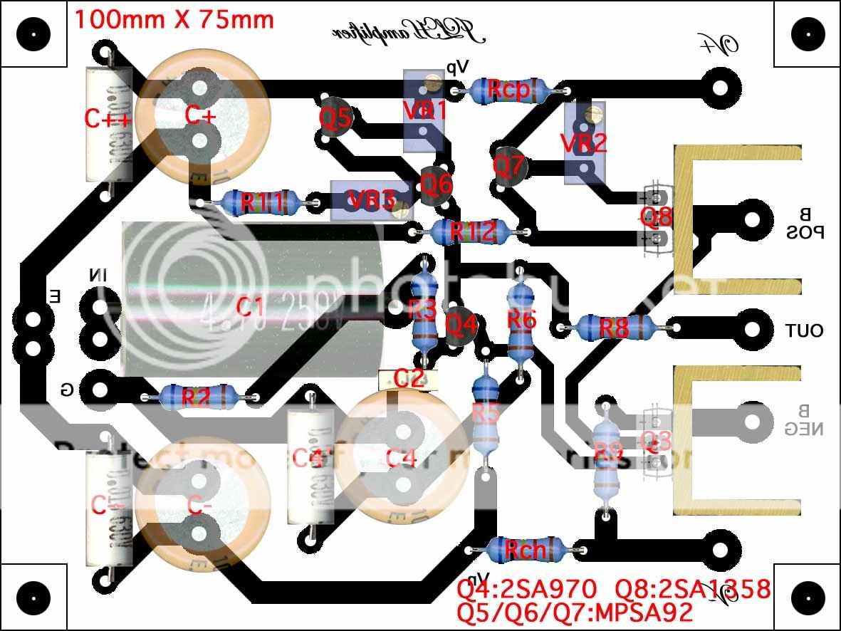
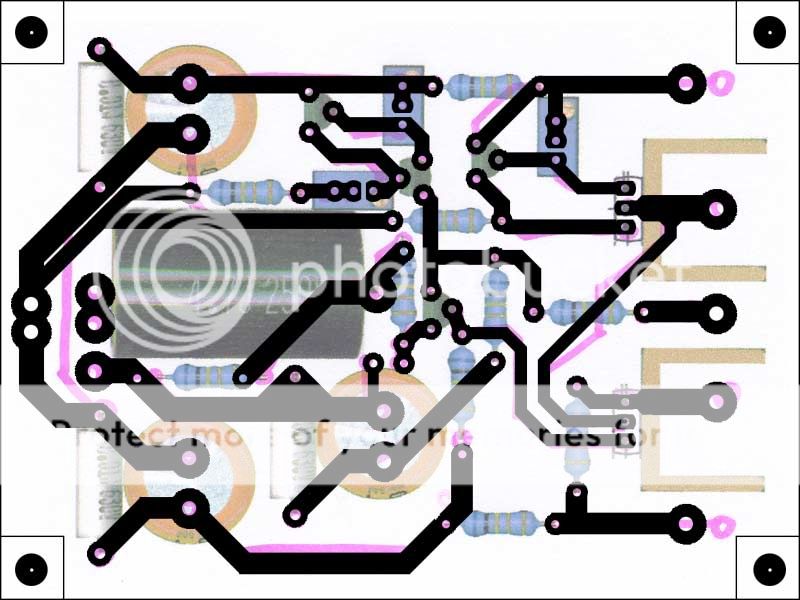
No, the earlier one is better. U should make branches at the capacitor.
3 branches for Q5, VR1 and Rcp
2 branches for R5. Rch
Connection E should go to C- first and then to C+
Power xtors should get connection from filter Cs
I am late, but I should answer. Never got the reminder.
Gajanan Phadte
how about this?
No, the earlier one is better. U should make branches at the capacitor.
3 branches for Q5, VR1 and Rcp
2 branches for R5. Rch
Connection E should go to C- first and then to C+
Power xtors should get connection from filter Cs
I am late, but I should answer. Never got the reminder.
Gajanan Phadte

- Home
- Amplifiers
- Solid State
- JLH 10 Watt class A amplifier