information....
this is the last attempt of building JLH.
I build 5 jlh`s last months.
with different parts quality:
1: standard part quality 30 watt
2: standard parts quality 10 watt
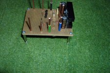
3: 10 watt w. audionote resistors/all transies matched
4: 10 watt w.dale resistors all /transies matched
4: 10 watt w.vishay s102k resistors/ all transies matched
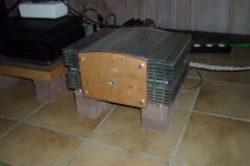
Toroid is a 800 VA one per side
PSu is a capacitance multiplyer (no pic yet availlable) with Elna cerafine and BlackGate kapacitors.
The last one is the best - perhaps the Psu made the last difference.
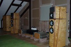
All in all a very special amplifier, hard to beat in sound quality of any ready made expensive transistor or tube amp.
Thanks to all who helped me in building this amp.
Ralf
this is the last attempt of building JLH.
I build 5 jlh`s last months.
with different parts quality:
1: standard part quality 30 watt
2: standard parts quality 10 watt
3: 10 watt w. audionote resistors/all transies matched
4: 10 watt w.dale resistors all /transies matched
4: 10 watt w.vishay s102k resistors/ all transies matched
Toroid is a 800 VA one per side
PSu is a capacitance multiplyer (no pic yet availlable) with Elna cerafine and BlackGate kapacitors.
The last one is the best - perhaps the Psu made the last difference.
All in all a very special amplifier, hard to beat in sound quality of any ready made expensive transistor or tube amp.
Thanks to all who helped me in building this amp.
Ralf
tschrama said:Do you realize that you have created a unique, truly unique output stage... I really dare anyone to search and find such a BJT/MOSFET triangle output stage
the reason I played with the circuitry in spice for quite sometime before actually making it is that I had never seen something like this and I wanted to utilize my inventory of irfs,
")
paulb said:It makes me wonder what the FET version would be like with the full capacitance multiplier power supply that apparently makes a big difference.
I have never listened to a BJT version of the JLH so I don't know how the MOSFET version compares against it. However, hum is absolutely NOT a problem with my version so I don't know how the cap multiplier would have worked or benefited the amp.
As to other improvement, I think most of them relate to hum. I did simulate quite a few versions of CCS to replace the bootstrap and I found no circuitry that will yield better THD figures.
But then THD figures aren't anything for an amp,
Re: information....
Holy Smoke Ralf,
5 pairs of JLH in a month! I did one pair in 15 months! You are going to beat Peter Daniel's productivity
;
Congrates!
The two PSU I experienced so far, one is the exact layout of the regulated psu in the original JLH for ESL with very good parts, the other is the CLC standard parts. I prefer the CLC psu since they both provide the about the same sound quality, but the CLC psu runs a lot cooler and a lot cheaper, though it is also a lot bigger in size.
Can you show us the cross over board of your speakers, they look impressive!
Nice one
Chris
ralf said:this is the last attempt of building JLH.
I build 5 jlh`s last months.
with different parts quality:
1: standard part quality 30 watt
2: standard parts quality 10 watt
3: 10 watt w. audionote resistors/all transies matched
4: 10 watt w.dale resistors all /transies matched
4: 10 watt w.vishay s102k resistors/ all transies matched
Toroid is a 800 VA one per side
PSu is a capacitance multiplyer (no pic yet availlable) with Elna cerafine and BlackGate kapacitors.
The last one is the best - perhaps the Psu made the last difference.
All in all a very special amplifier, hard to beat in sound quality of any ready made expensive transistor or tube amp.
Thanks to all who helped me in building this amp.
Ralf
Holy Smoke Ralf,
5 pairs of JLH in a month! I did one pair in 15 months! You are going to beat Peter Daniel's productivity
; Congrates!
The two PSU I experienced so far, one is the exact layout of the regulated psu in the original JLH for ESL with very good parts, the other is the CLC standard parts. I prefer the CLC psu since they both provide the about the same sound quality, but the CLC psu runs a lot cooler and a lot cheaper, though it is also a lot bigger in size.
Can you show us the cross over board of your speakers, they look impressive!
Nice one
Chris
I did simulate quite a few versions of CCS to replace the bootstrap and I found no circuitry that will yield better THD figures.
That's weird... The MOSFET's are high impedance devices and voltage driven.. so there's no need for either a CCS or Bootstrap, .. it doesn't need current (or much less).. but there is a need for a voltage swing at the upper MOSFET gate.. .. this all seems very strange to me.. Are you sure that your amplifier works OK, have you checked the current swing through both MOSFETs.. they should be mirrors of each other... I think you just made a SE amplifier instead of a Push-Pull .. that would explain your low power and early but gracefull clipping...
Could you post a schematic with component values?
Best regards,
Thijs
tschrama said:That's weird... The MOSFET's are high impedance devices and voltage driven.. so there's no need for either a CCS or Bootstrap, .. it doesn't need current (or much less).. but there is a need for a voltage swing at the upper MOSFET gate.
isn't that precisely what the bootstrap / CCS does for the upper MOSFET? providing high voltage gain for the driver.
at low Iq (for the driver), the upper half of the waveform distorts heavily: it is more like a triangle than a sine wave. This is very similar to if you feed the amp with a high frequency signal (like over 250khz). I suspect that it has something to do with the high gate capacitance of the IRF devices and at high frequency the capacitance starts to suck current away so if you idle the driver at high current it you minimize the impact of the gate capacitance (via its "current").
tschrama said:Are you sure that your amplifier works OK, have you checked the current swing through both MOSFETs.. they should be mirrors of each other... I think you just made a SE amplifier instead of a Push-Pull .. that would explain your low power and early but gracefull clipping...
I shorted the gate / source of each of the mosfet with a 470ohm resistor to make sure that they worked. I got lower volume sound. And the decrease is greater when I shorted the upper MOSFET. so both are working and the top is providing more gains than the bottom MOSFET. I did that orginally to see which of the two are the primary contributor to gain.
Unfortunately, I didn't have a scope so I cannot be 100% sure.
tschrama said:Could you post a schematic with component values?
Best regards,
Thijs
it is post 515 in this very thread. the only thing changed is that gate stoppers for the mosfets (220ohm vs. 0.22ohm in the schematic).
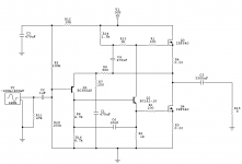
OK here it goes....
after reading D. Self's book about this output stage I got thinking..
1]
The base inpedance of the second transistor is indeed low .. offcourse dependend on the Hfe, but around 8K Ohm.. and since this is parrallel with the 10K collector resistor of first transistor, open loop gain must really suffer...but since the lower MOSFET gate is a high impedance node (not like the 2N3055 version) things can be improved... using a 1K resistor to the gate of the lower MOSFET improves things a bit.. from 8 K to 52 K
2]
Bootstrapping the collector load of the first transistor improves things even more... from 10K to 320 K .. openloop is now more than doubled
3]
lowering the 0.47 R resistor to 0.22 gives a somewhat higher openloop gain.. the voltage drive for the lower MOSFET is allmost halved...
4] lowering the feedback network from 200/2K to 100/900 give somewhat higher openloop gain and a bit more feed back
5]allthough this is tricky.. loweriung the gate resistor from 220 to 100 Ohm help abit against too must openloop phase shifts and improves closeloop phase margin..
results
1Watt ... THD < -90dB
9 watt .. THD < -85dB
which is more than 20dB less.... the standard version..
Well .. lets hear it .. what do you think.. I actually think that bootstrapping the collector load of the first transistor is very nice .. it's a feature only availale with this MOSFET output stage, easy to implement and a garanteed enhancement of openloop gain...
I think there's a lot more to this topology and still hope that someone else tinks it over too...
Regards,
Thijs
I'm sorry to kind of bump this thread, but it seems that due to my post showing up later (since I'm new), nobody has noticed it.
Could you guys please take a look? Here is the post: http://www.diyaudio.com/forums/showthread.php?postid=282346#post282346
Thanks!
Could you guys please take a look? Here is the post: http://www.diyaudio.com/forums/showthread.php?postid=282346#post282346
Thanks!
tschrama said:1]
The base inpedance of the second transistor is indeed low .. offcourse dependend on the Hfe, but around 8K Ohm.. and since this is parrallel with the 10K collector resistor of first transistor, open loop gain must really suffer...but since the lower MOSFET gate is a high impedance node (not like the 2N3055 version) things can be improved... using a 1K resistor to the gate of the lower MOSFET improves things a bit.. from 8 K to 52 K
I will need to go through my simulation. It might be too small (4ma roughly, had I used the same resistors in my set-up).
tschrama said:2]
Bootstrapping the collector load of the first transistor improves things even more... from 10K to 320 K .. openloop is now more than doubled
this is a very nice concept, and probably the single biggest improvement I think. I will play with mine for a while to see what I can get.
thanks for putting your thoughts into this. Hopefully we can collectively make it a better amp benefiting the whole community.
Thanks.. i really like playing with citcuits like this ... I agree that the bootstrapping is the most ellegant improvement.... utilizing the MOSFET properties better...
I'm going to further analyze this JLH 'triangle' output stage.. and see what consequeces there are using the MOSFETS...
Let me hear what you get out pf your sim.... maybe you could try the bootstrapping in real life?
PS
I still don't understand how the 2 MOSFETS in your version share the AC current that equal .. ?
tschrama said:
I really hope someonemore knowlegbeble can comment on the BJT/MOSFET exchange in a JLH 10W Class A 1969 amplifier... it makes my head spin..
Hi millwood and tschrama. I think I can feed you some information on this circuit and post here my own version of MOSFET development, somewhat based on JLH class A idea, which I've designed in 1992 and this amplifier still working quite happily in my daughter's room
. Thought my amp was not built as class A, it could be easily converted into a proper class A amp by reducing the supply voltage and increasing the idle current - no other changes are needed for the circuit. I did publish this circuit in 1998 in the "Radiohobby" magazine as an illustration to a further development of it (a version of this later circuit could be found here: http://www.diyaudio.com/forums/showthread.php?s=&threadid=14320 ). The sound of this amp is very sweet... .First, thought, a couple of buckets of cold water
for millwood:Your circuit loses a main attraction of JLH - it's symmetry. JLH is a proper push-pull circuit, working on the balance of the currents, as output bipolar transistors controlled by their respective base currents, and the driver redistributes the currents according to the signal. In your circuit, lower MOSFET is almost a current source, so the circuit is essentially an SE one. MOSFETs controlled by the gate-source VOLTAGE, so JLH way of control does not work. Also your circuit could be thermally not very stable and quite sensitive to the power supply variations and ripple.
Have a look at my circuit here and ask questions
- I would be happy to answer.Cheers
x-pro (Alex)
Attachments
Hi x-pro,
Thanks for your reply. Indeed I has some concenrsns similar to yours, but I don't have it comppletely figured out yet... I really like the way you explain the topology .. redistrubuting current ..
I'll have a look at your circuits and I'm sure I have some, several, dozens of questions...
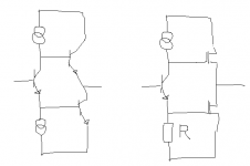
Mean while I have drawn the 'JLH 10W Class A Triangle output stage' (lets call it triangle in short) in simplified form to analyze.. one version fo BJT (assume equal Hfe) , and one for MOSFET (assume equal transductance)
I'll attache a drawring... maybe it helps ... maybe not..
Thanks for your reply. Indeed I has some concenrsns similar to yours, but I don't have it comppletely figured out yet... I really like the way you explain the topology .. redistrubuting current ..
I'll have a look at your circuits and I'm sure I have some, several, dozens of questions...
Mean while I have drawn the 'JLH 10W Class A Triangle output stage' (lets call it triangle in short) in simplified form to analyze.. one version fo BJT (assume equal Hfe) , and one for MOSFET (assume equal transductance)
I'll attache a drawring... maybe it helps ... maybe not..
Attachments
- Home
- Amplifiers
- Solid State
- JLH 10 Watt class A amplifier