tlf9999 said:I would stick to the original JLH topology and tweak one at a time to see how it works. My experience of playing with JLHs is that they are excellent in producing bass.
IRF510 should be plenty enough for this kind of amplifier.
a few quick comments:
c) the feedback networks are a little bit too complicated.
d) I am not sure if this really is a JLH, with so many changes.
e) is there inherent DC offset on the speaker?
Good luck.
hi,tlf9999:
yes,I think so that the IRF510 is enough for this class-ab amp;
c)I think there is more suitable NFB n.w. in my circuit...and I save a cap(330uF) which make it more HI-FI;
d)I think JLH's collection is it's phase permute stage;
e)yes,very small DC offset in the speaker;
thank you for your opinion!
enjoy!
hello,Mr.Graham:Graham Maynard said:Hi DarkHorse.
Assuming that all your other amplifier capacitors are good for a really low response, can I suggest you try powering up with parallel connected 2x10mF + 2m2F capacitors feeding the loudspeaker, and then listen to bass reproduction as you switch the 2x10mF out of and back into series connection.
you are so professional in simulation.but I think all speaker are different in their parameters,so I think using a 8ohm resistor as load is OK,because I don't know my speaker unit's parameters...

regards!
WINCO
hi,Dragon2:Dragon2 said:Hi Darkhorse
Like M.Maynard i suggest that you do split power supply to put off the output cap unless you want to install a bigger cap(25000uf)
Have a good day
your mean is using OCL(+/- power supply)...?
I know that is good idea,but my favourite is OTL circuit...haha
enjoy!
WINCO
tlf9999 said:I ran my JLH's into a 3300uf output cap and they gave very strong bass.
My experience is that higher capacitors don't really gain much in terms of bass.
I suspect the lack of bass is due to something else.
this let me feel so puzzle...from it's analysis diagram it can't proces much bass...but you say that it can & even say very strong...

I think I have to build this amp(Post #1234) which has new NFB networks this sunday.I wish it's bad character can be corrected.
wait for my test result please!
have fun!
WINCO

off the topic but still
guys - hi,....
I have made an hood amp much like sch attached. It has 2sa970 in front and mj15003 at the back. Everything else, BD139, BD140, Vr1=2k is pretty much the same. I have 2 big cap's 39kuF to filter the power suplly.
There is much to work with the amp - it is still in the prototype fase.....
Question: how to determine that the heatsinks are to hot? I can hold my hand on my heatsinks for 10sec but must concentrate not to remove hand.... I can't touch my transistors. They are to hot. (well I can but can't hold my hand on it). Is it to hot for the trasistors?
Also - I have seen that the amp I have made work better when the current is set on 1.5A per channel. I think that it would be better to set it on 2A but when I do that the amp doesn't sound that good. How is that?
Thanks for Your time and future replies.....
best regards
daniel
Attachments
Re: off the topic but still
Hi sparkle,
I have build a DOZ which is similar to JLH and your description is exactly my experience. I think as long as you monitor the bias current and it stablises once everything heats up then everything is OK. A little scary the heat these class A things generate when you're used to class AB.
You can always increase the size of your heatsinks or use a fan if you're not comfortable.
sparkle said:Question: how to determine that the heatsinks are to hot? I can hold my hand on my heatsinks for 10sec but must concentrate not to remove hand.... I can't touch my transistors. They are to hot. (well I can but can't hold my hand on it). Is it to hot for the trasistors?
Also - I have seen that the amp I have made work better when
Hi sparkle,
I have build a DOZ which is similar to JLH and your description is exactly my experience. I think as long as you monitor the bias current and it stablises once everything heats up then everything is OK. A little scary the heat these class A things generate when you're used to class AB.
You can always increase the size of your heatsinks or use a fan if you're not comfortable.
Heatsink
Hi Darkhorse
Yes i mean OCL.
I like too OTL but you must have high impedance speakers.
The bass with an OTL is not as good as with transistors(bip).
I have a JLH amp since 4 years and i have tried many output caps and many brands. The better result was with 22000uf bypassed with 2200uf and 10 polystyrene cap.
Have a good day.
Hi Sparkle
When you desigh class a amp. you should measure heatsink temp. with temperature probe and multimeter.
60 deg C. is the maximum on the heatsink for reliable operation.
If the transistor is a lot hotter than the heatsink, your heat transfer is bad ( Check your hardware ) and it must be the reason your amp is less good at 2A. because the transistor is too hot. I have tried transistors at
80 deg heatsink temp and is sound less good (sparkle has gone)
The hfe is higher a high temp.
Have a good day
Hi,
thnx for the reply - I will try to get some multimeter with a probe but it would be dificult - I only have my thumb
well, the amp was running at 2A now is on 1.5A. Sound is better now.
Does anyone knows how much heat does a human thumb considers hot and how much only warm - i think that I have read that somewhere....
regards
daniel
Hi,
I have measured the temperature of the heatsinks - 50 degrees, the mj15003 are around 80 degrees. Is this to hot for the mj15003?
best regards
p.s. one more thing - is there a transistor similar to the mj15003 that work here the same as mj15003 but has to247 or similar housing that can be mount directly on the heatsink - i have one l profile that i have used to mount transistor and it is 5mm thick - i belive that this is the problem - if i could find transistors - maybe mj15003 in to247 or similar that i could mount on the heatsink directly that would be wonderful

DarkHorse ?
Is that something you really wanna build? haven't you read the thread?
-The irf510 won't last, even irf540 have a hard a time due to their small contact area
- the phase-splitter have to be equal, read the thread
- the gate-snopper need to be about 150 Ohm, not 43 .. hf oscilation will happen, and it will depend on the Drain-to-Source voltage.. you need to test is at full output.
why don't you start from the mosfet JLH that has been published , build and tested, and go from there?
Darkhorse, not exactly sure what your problems are. Here is a project I did a while back.
It is the JLH topology, with a slight modification on the output so that I can use big MOSFETs (irfp140 in this case), without overloading the driver stage because of high gate capacitance of the IRF device. You can easily change it to accomodate your own MOSFETs.
It has been built successfully with various devices, and has very strong bass.
You can change your existing circuitry to this quite easily.
You can also run it with +/- rails as well. In that case, you don't need the output capacitor.
Attachments
tschrama said:DarkHorse ?
Is that something you really wanna build? haven't you read the thread?
-The irf510 won't last, even irf540 have a hard a time due to their small contact area
- the phase-splitter have to be equal, read the thread
- the gate-snopper need to be about 150 Ohm, not 43 .. hf oscilation will happen, and it will depend on the Drain-to-Source voltage.. you need to test is at full output.
why don't you start from the mosfet JLH that has been published , build and tested, and go from there?
hi,tschrama:
in fact,I really want to build one of mosfet JLH amp,because it can works in class-ab and it sounds as good as jlh1969...I reference X-PRO's circuit and accept your argument...so I gather together...
I think I can design & build one perfect and more simple JLH mosfet amp for myself,so I start ...
don't look down IRF510,I have tesing it and IRF540,and I find IRF510's sound is more lovely than IRF540's...
I have researched with X-PRO's circuit,and you can see it's phase-splitter upper using 30V,and lower using 25V,total is Ucc(55V).and I have do many simulation,you have no need to doubt it's rationality.
protect mosfet's integral effect is why the gate-snopper I use 43ohm...and change this gate-resistor isn't modify it's bass range.
and I have simulation X-PRO's circuit,it seems to my posted Post #1213,I just only do some modification with it's ccs...
so,their result is on the same way...
I recommend X-PRO's and the circuit in Post #1213.their mediant & treble is perfect!only short of some bass.
regards
WINCO
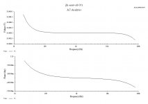
tlf9999 said:Darkhorse, not exactly sure what your problems are. Here is a project I did a while back.
It is the JLH topology, with a slight modification on the output so that I can use big MOSFETs (irfp140 in this case), without overloading the driver stage because of high gate capacitance of the IRF device. You can easily change it to accomodate your own MOSFETs.
It has been built successfully with various devices, and has very strong bass.
You can change your existing circuitry to this quite easily.
You can also run it with +/- rails as well. In that case, you don't need the output capacitor.
hi,tlf9999:
thank you for your circuit and ac analysis diagram...
but I can't find the thing what I expected in the ac analysis,that is not to say the your circuit can't process bass well,perhaps is my speaker unit too hard to process bass,their are 3" unit...
but they all sounds good driving by my ZEN2 amp...
I don't know...it is adoubts and suspicions.
regards
WINCO
hello,I come back!!!
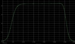
many days I was thinking the way to let JLH mos version has more strong bass...
now I got it!I feel so happy and excited!!!
because I finally let 20Hz turn up,full range output curve now is the shape what I want,although just simulation now,but I got this result is not easy and I nearly give up this project...
thank you,the people who care this thread and help me during this time...
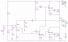
look the updated schematics(warnning: no examination now):
many days I was thinking the way to let JLH mos version has more strong bass...
now I got it!I feel so happy and excited!!!
because I finally let 20Hz turn up,full range output curve now is the shape what I want,although just simulation now,but I got this result is not easy and I nearly give up this project...
thank you,the people who care this thread and help me during this time...
look the updated schematics(warnning: no examination now):
Attachments
- Home
- Amplifiers
- Solid State
- JLH 10 Watt class A amplifier