something has change in my sample
In my sample:
RP1 is 220K(set to 100K at first);
C4 is 22uF;
R2 is 120K;
C1 is 4.7uF("ERO" MKT cap.);
Q1 is 2SA970(hfe=287);
R5 is 5.1Kohm;
C5 is 22pF;
V1 is 42V(power voltage);
MU-1 is about 3V;
MU-2 is 19.5V(when Ucc is 42V);
MA-1 is about 100mA.
In my sample:
RP1 is 220K(set to 100K at first);
C4 is 22uF;
R2 is 120K;
C1 is 4.7uF("ERO" MKT cap.);
Q1 is 2SA970(hfe=287);
R5 is 5.1Kohm;
C5 is 22pF;
V1 is 42V(power voltage);
MU-1 is about 3V;
MU-2 is 19.5V(when Ucc is 42V);
MA-1 is about 100mA.
tlf9999 said:if you really care about THD, you may want to use BJTs in front of the MOSFETs.
I have tried using Moto drivers in front of Fairchild power MOSFETs (FQA series) in various set ups including JLH and they sound very good to my ears.
hi:
I don't really care about it's signed THD,but it's distorsion lower than 0.1% is needed!
in my builded sample,it sounds very good!but just in Mediant & treble range...I don't satisfying it's bass range(lower than 100Hz),
and I think the JLH1969 has same problem!?
short of bass let my sample amp lost some impressive...
nothing is perfect ,isn't it?
...
regards
WINCO
tlf9999 said:Darkhorse, I was a little surprised in hearing that your JLH didn't reproduce bass well. variants of JLH that I have built all do well in that department.
maybe the issue you ran into is somewhere else?
I don't know JLH1969's bass character is well or not...
but in my simulation the amp I build has not perfect bass range,
so I know this before I build it...
I think I have to research it's topology at coming days...
in fact,I have a doubt with it's negative feedback loop,you can see the loop didn't include output cap(6800uF),so it will lead this cap need to be more large value(more than 10000uF is better),
I will do some simulation with JLH1969 amp circuit tonight,and I can reference it's sound range...
thank you!
regards
WINCO
???chris ma said:With such a small power supply and such a small no baffle speaker I can understand why there is no bass
hi,what make you think that my power supply is "small"...???
my transformer has about 400VA's power...and I use a 40A/400V bridge,2*4700uF/63V cap,is this call "small"???
I have test this power supply with my ZEN2,and it's bass comes well,that is to say:there hasn't any problem with my power & speaker unit...
so I think there is some thing diffent to BJT version...
regards
WINCO
Transistor substitution
Hi,
Has anyone tried transistor substitution from 2SA970 to BC560C? What is the disadvantage of this substitution? i've build mine with BC560C cos' cant find the eagle footprint for 2sA970. Where can I find this?
Also can I replace 2SA1358 and 2SC3421 with MJE15032 and MJE15033?
Thanks.

Hi,
Has anyone tried transistor substitution from 2SA970 to BC560C? What is the disadvantage of this substitution? i've build mine with BC560C cos' cant find the eagle footprint for 2sA970. Where can I find this?
Also can I replace 2SA1358 and 2SC3421 with MJE15032 and MJE15033?
Thanks.
Re: Transistor substitution
I am not sure if I understand this. You don't need to pick up the feedback signal after the output capacitor as part of the feedback network already has a DC-blocking capaitor.
in general, solid state circuits are surprising robust with regards to compoenent choices. I have built the JLH (and others) with a wide array of transistors without any ill effect. Just make sure that you replace like devices with like devices: small signal transitors with small signal transistors, etc.
DarkHorse said:in fact,I have a doubt with it's negative feedback loop,you can see the loop didn't include output cap(6800uF),so it will lead this cap need to be more large value(more than 10000uF is better),
I am not sure if I understand this. You don't need to pick up the feedback signal after the output capacitor as part of the feedback network already has a DC-blocking capaitor.
Ipanema said:Has anyone tried transistor substitution from 2SA970 to BC560C?
in general, solid state circuits are surprising robust with regards to compoenent choices. I have built the JLH (and others) with a wide array of transistors without any ill effect. Just make sure that you replace like devices with like devices: small signal transitors with small signal transistors, etc.
Hi DarkHorse,
I always watch the JLH 10W thread, and I have followed your Mosfet based experiments here.
You mention the bass not being perfect. This is due to the series output capacitor.
Anyone used to correctly performing amplifiers that do not use a series output 'C' do notice the difference. Its not an amplitude thing, but relates to NFB loop generated control of the bass driver back-EMF; with a capacitor it is in quadrature.
You think about picking up NFB after the capacitor to cure the imperfect bass, but this will lead to a phase changed peak in the sub-bass region. (Too many 'C's in the feedback path.)
Possible cures - very high value series output capacitor, use the later JLH class-A circuit, or direct couple with a differential input stage.
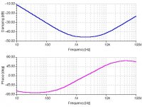
I have simulated your IRF510 circuit for damping amplitude/phase at 8 ohms; as attached. You can see that the NFB loop generated bass 'cone' control is going to be out of phase with loudspeaker generated back-EMF at low frequencies.
Also note that when you use Mosfets in the JLH class-A arrangement, that their gate capacitance creates a need for Miller stabilisation at the splitter transistor, and both sets of path capacitances shift the phase response of the hf damping. With your amplifier it is 50 degrees, with bipolars in class-A approx 15 degrees.
Cheers ........... Graham.
I always watch the JLH 10W thread, and I have followed your Mosfet based experiments here.
You mention the bass not being perfect. This is due to the series output capacitor.
Anyone used to correctly performing amplifiers that do not use a series output 'C' do notice the difference. Its not an amplitude thing, but relates to NFB loop generated control of the bass driver back-EMF; with a capacitor it is in quadrature.
You think about picking up NFB after the capacitor to cure the imperfect bass, but this will lead to a phase changed peak in the sub-bass region. (Too many 'C's in the feedback path.)
Possible cures - very high value series output capacitor, use the later JLH class-A circuit, or direct couple with a differential input stage.
I have simulated your IRF510 circuit for damping amplitude/phase at 8 ohms; as attached. You can see that the NFB loop generated bass 'cone' control is going to be out of phase with loudspeaker generated back-EMF at low frequencies.
Also note that when you use Mosfets in the JLH class-A arrangement, that their gate capacitance creates a need for Miller stabilisation at the splitter transistor, and both sets of path capacitances shift the phase response of the hf damping. With your amplifier it is 50 degrees, with bipolars in class-A approx 15 degrees.
Cheers ........... Graham.
Attachments
Other observations aside, I think your choice of the IRF510
is probably the biggest reason you may not like the bass
character. I suggest you try something like 540's and see if
it makes a difference. You will probably want to re-adjust your
compensation capacitance if you try it.
I've played with constant current sources such as your JFET off
the input device on this topology, and I've not been thrilled. It
might produce better numbers, but I think you could try a
resistor instead, and see what you get.
Graham Maynard said:Hi DarkHorse,
I always watch the JLH 10W thread, and I have followed your Mosfet based experiments here.
You mention the bass not being perfect. This is due to the series output capacitor.
Also note that when you use Mosfets in the JLH class-A arrangement, that their gate capacitance creates a need for Miller stabilisation at the splitter transistor, and both sets of path capacitances shift the phase response of the hf damping. With your amplifier it is 50 degrees, with bipolars in class-A approx 15 degrees.
Cheers ........... Graham.
Nelson Pass said:
Other observations aside, I think your choice of the IRF510
is probably the biggest reason you may not like the bass
character. I suggest you try something like 540's and see if
it makes a difference. You will probably want to re-adjust your
compensation capacitance if you try it.
I've played with constant current sources such as your JFET off
the input device on this topology, and I've not been thrilled. It
might produce better numbers, but I think you could try a
resistor instead, and see what you get.
think you,Mr.Graham & Mr.Pass:
first,I agree with Graham's point,using large value of feedback cap & output cap,this is most easy way to improve it's bass character.
And I really like IRF540 transistor,It has low output resistor...but I hate it's about 1700pF's gate capacitance...it due to Hi-Frequency's waveform freaky...because it's driver current isn't strong(each IRF510 got about 4~5mA driver current ),so I have to choose low power&low gate cap.(about 200pF) IRF510...
and Mr.Pass said:using a resistor to instead of CCS,I think so!
because I have met the same things & get same recognition.
here is my IRF510 circuit's(according to my sample's value) AC ANALYSIS diagram(some difference with Mr.Graham,I think that is the software's problem?):
Attachments
Hi DarkHorse,
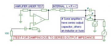
Put a nominal input sourse resistance in place of your signal generator at amplifier input, say 100 ohms.
Move your signal generator to the earthy side of your 8 ohm amplifier load resistor, and analyse how the amplifier could behave in the presence of crossover/loudspeaker generated back-EMF.
Do this with several amplifier types and you will observe patterns arising that relate to topology, device types, stabilisation components, numbers of stages within global loop etc.
For cleanly controlled damping you need a flat phase response.
An increasing angle or quadrature at hf, especislly with a low damping factor and low bias class-AB, can lead to crossover section/loudspeaker generated back-EMF overcoming a portion of quiescent bias.
Output capacitor based back-EMF problems can arise with the 4 transistor JLH, but not the later directly coupled version. All other capacitors need to have sufficient value for good low frequency performance, and with today's lower frequencies original JLH values can be increased.
Don't forget that you can also place your virtual signal generator in series with the rail supplies to check out common mode rejection characteristics.
Cheers .......... Graham.
hi all:
I have say that I was unsatisfy with it's negative feed back networks...perhaps it was still suitable to BJT version(JLH1969),
but I don't comfortable with it in MOS version...So I have to do some modification with my IRF510 circuit,I think it should works well,maybe not.
here is my IRF510 circuit schematics,please do me a favor to check it's disadvantage,thank you!
Attachments
I would stick to the original JLH topology and tweak one at a time to see how it works. My experience of playing with JLHs is that they are excellent in producing bass.
IRF510 should be plenty enough for this kind of amplifier.
a few quick comments:
a) I am not sure how the driver stage is biased: on one hand, it is biased by the lower mosfet's Vgs (say 4v over 1kohm->4ma which seems to be very small). on the other hand it is also biased by Q4. it might be easier to replace Q4 with just a resistor (a JLH-styled bootstrap network isn't really needed to get this to function).
If you dial up the bias, you may have to use a beefier driver transistor. I used a 2119x series transistor for mine, or if you want, use a IRF510.
b) R8/R9 are probably OK but I tend to use 110 or 220 ohm resistors there.
c) the feedback networks are a little bit too complicated.
d) I am not sure if this really is a JLH, with so many changes.
e) is there inherent DC offset on the speaker?
f) if you are concerned about gate capacitance of larger output devices, you can use dedicated BJT drivers in front of them. I did so on FQA27N25 (Cgs of 1900pf typical). Let me know if you would like to see a schematic of it.
Good luck.
Hi DarkHorse.
A real-life loudspeaker generates back-EMF and thus its current is not phase linear, especially around driver/cabinet resonance.
When there is a capacitor in series with the loudspeaker then the amplifier's cone control also becomes phase shifted, and the bass drive sounds weak wrt mid/treble, even though the amplitude is little changed.
Assuming that all your other amplifier capacitors are good for a really low response, can I suggest you try powering up with parallel connected 2x10mF + 2m2F capacitors feeding the loudspeaker, and then listen to bass reproduction as you switch the 2x10mF out of and back into series connection.
The test I suggested in my last post is designed to look at the amplifier's output impedance by making an AC analysis looking back into the amplifier. This comprises NFB loop generated series resistance, capacitance and inductance plus any externally added series impedances. It also gives you the damping factor wrt. say 8 ohms. See attached
Attachments
Hi Darkhorse
You need more powerfull transistors: IRF510 is good for input cap. but mosfets sing only when you put a lot of current. If you do that, the 510 will become hot and with 42v on the rail... You must use something like the IRF540-640 or IRFP140.
Like M.Maynard i suggest that you do split power supply to put off the output cap unless you want to install a bigger cap(25000uf)
You will have to get a bigger driver to satisfy the higher input cap of these bigger mosfets.
I have often tried jfet at the input and the better result i have obtained was with a cascode followed by a buffer.
Have a good day
- Home
- Amplifiers
- Solid State
- JLH 10 Watt class A amplifier