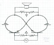
The amplifier disclosed here is actually a Circlotron, implemented with bipolar transistors. I call it Infinitron because I found it easier to visualize Circlotron topology not as a circle, but more like a figure 8, or even better, the symbol for INFINITY (see Logo attachment). This same visualization follows to the schematic, and to a certain extent, the PC card.
If one sees a schematic resemblance to Jean Hiraga's 'le monstre', it is not a coincidence. My original plan was to bridge a pair o'monsters' to realize a balanced amp. This 'monster pair' idea eventually morphed into Infinitron.
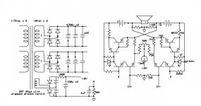
Infinitron is running class A, with about 1 Amp Iq. Power out is a nominal 20W. Output BJTs are KSA1220Y/2SC5200. The input is a MAT02 with BC550 cascodes, but matched BC550s would work as well for the inputs.
I'm quite pleased with the performance and stability of this amp. I have been using it with a Cambridge Audio DacMagic+ for over a year now, with no issues at all.
Enjoy!..
Attachments are; Infinitron logo, schematic, 20kHz square wave trace, completed 2ch amp in a gutted pro-amp enclosure.
If one sees a schematic resemblance to Jean Hiraga's 'le monstre', it is not a coincidence. My original plan was to bridge a pair o'monsters' to realize a balanced amp. This 'monster pair' idea eventually morphed into Infinitron.
Infinitron is running class A, with about 1 Amp Iq. Power out is a nominal 20W. Output BJTs are KSA1220Y/2SC5200. The input is a MAT02 with BC550 cascodes, but matched BC550s would work as well for the inputs.
I'm quite pleased with the performance and stability of this amp. I have been using it with a Cambridge Audio DacMagic+ for over a year now, with no issues at all.
Enjoy!..
Attachments are; Infinitron logo, schematic, 20kHz square wave trace, completed 2ch amp in a gutted pro-amp enclosure.
Attachments


Last edited:

Hi Polyphase !
Thanks for sharing that nice SS Circlotron A class amp design !
And few question :
- that circle with arrow inside represent some CCS unit ?
- it is possible to run that amp in SE mode ?, but not only in balanced mode , with let`s say IN (-) connected to ground .
Thanks for sharing that nice SS Circlotron A class amp design !
And few question :
- that circle with arrow inside represent some CCS unit ?
- it is possible to run that amp in SE mode ?, but not only in balanced mode , with let`s say IN (-) connected to ground .
My pleasure.
-Yes, that is indeed a current source. It should be adjustable between 2ma and 4ma,
as this is what sets Iq.
-Yes, it will run in SE mode. IN(-) should be grounded via an input capacitor.
-Yes, that is indeed a current source. It should be adjustable between 2ma and 4ma,
as this is what sets Iq.
-Yes, it will run in SE mode. IN(-) should be grounded via an input capacitor.
Polyphaze thanks for your answer !
All is clear now !
With that CCS in tail of input cascoded LTP SE mode is quit possible , ( but as always balanced drive mode is preferable option over SE mode for this type of basically fully balanced amp .) , and yes I like that global balanced negative current feedback design solution .
All is clear now !
With that CCS in tail of input cascoded LTP SE mode is quit possible , ( but as always balanced drive mode is preferable option over SE mode for this type of basically fully balanced amp .) , and yes I like that global balanced negative current feedback design solution .
Sure. The current iteration, rev0, it not ready for prime time, as it has some 'cuts and jumps', no silkscreen etc. Rev1.0 will be ready soon though.
super !
A 100W 4ohm version in AB is possible ?
Thanks..
While a 100W version is certainly possible, I never considered AB operation in the design. I suspect that it would not do well.
beautiful amp - the concept sketch triggers mainly a slot car set in my feeble mind......
Thanks for the levity. I laughed out loud.
Ok thanks ,we will wait for this.🙂Sure. The current iteration, rev0, it not ready for prime time, as it has some 'cuts and jumps', no silkscreen etc. Rev1.0 will be ready soon though.
Good approach and simple design. Check out also the schematics from post #4 and #14 underThe amplifier disclosed here is actually a Circlotron, implemented with bipolar transistors. I call it Infinitron because I found it easier to visualize Circlotron topology not as a circle, but more like a figure 8, or even better, the symbol for INFINITY (see Logo attachment). This same visualization follows to the schematic, and to a certain extent, the PC card.
If one sees a schematic resemblance to Jean Hiraga's 'le monstre', it is not a coincidence. My original plan was to bridge a pair o'monsters' to realize a balanced amp. This 'monster pair' idea eventually morphed into Infinitron.
Infinitron is running class A, with about 1 Amp Iq. Power out is a nominal 20W. Output BJTs are KSA1220Y/2SC5200. The input is a MAT02 with BC550 cascodes, but matched BC550s would work as well for the inputs.
I'm quite pleased with the performance and stability of this amp. I have been using it with a Cambridge Audio DacMagic+ for over a year now, with no issues at all.
Enjoy!..
Attachments are; Infinitron logo, schematic, 20kHz square wave trace, completed 2ch amp in a gutted pro-amp enclosure.
http://www.diyaudio.com/forums/soli...-names-commercial-solid-state-amplifiers.html
so as this threads:
http://www.diyaudio.com/forums/soli...no-feedback-classab-buffer-5.html#post2337770 (post #45)
http://www.diyaudio.com/forums/soli...g-schemes-bipolar-transistor-circlotrons.html
Last edited:
Thanks for this. Some of these are familiar, some are not. I was particularly intrigued by the Russian 'Amphiton' that showed up on one of the links you provided. Another interesting DIY circlotron project, by Michael Rothacher, can be found here:
https://www.passdiy.com/project/amplifiers/build-the-amazing-fet-circlotron
https://www.passdiy.com/project/amplifiers/build-the-amazing-fet-circlotron
Hi polyphaze,
how did you choose the value for the 110ohm output resistor ?
Thanks
Best regards
Seb
how did you choose the value for the 110ohm output resistor ?
Thanks
Best regards
Seb
Well, the value of this resistor is not critical if within a range, but both need to be matched. The 110ohm are two 220 // as built, as I had them on hand. I have since determined that a higher value is better, maybe 220 to 330 if the input CCS is ~3ma.
Thanks for your answer.
is it better to listen or measure?
when you changed the value of the resistor, you set the output quiescent current again ?
I did some simulation on another diagram and I realized that increasing this value also increased the distortion.
http://www.diyaudio.com/forums/solid-state/261515-vssa-circlotron-11.html#post5536221
http://www.diyaudio.com/forums/solid-state/261515-vssa-circlotron-12.html#post5536808
Thanks for your interest.
For me, better to listen. As for Iq, (which should be ~1A for this design) it is a function of Iccs, and other components including these resistors on the output.
I don't see how increasing the value of these output resistors in my design (from the original 110R) could increase distortion as long as amp is in class A mode, but maybe I'm missing something. I do know from listening that distortion is quite low, and that the 'tweaks' shown in attached schematic have improved the listening experience.
Attachments

- Home
- Amplifiers
- Solid State
- I Call it INFINITRON