@Polyphase:
Please publish a more "beginner friendly" full circuit diagram with device numbers etc, and some build details/tips, and a thru-hole component PCB design. It will be of great help to people wanting to explore the Infinitron.
Thanks and regards.
Please publish a more "beginner friendly" full circuit diagram with device numbers etc, and some build details/tips, and a thru-hole component PCB design. It will be of great help to people wanting to explore the Infinitron.
Thanks and regards.

Hello..@Polyphase:
Please publish a more "beginner friendly" full circuit diagram with device numbers etc, and some build details/tips, and a thru-hole component PCB design. It will be of great help to people wanting to explore the Infinitron.
Thanks and regards.
OK, I will do this, give me a few days.
Yes, but the design works just as well from single ended sources. Just connect the (-) input pin to ground with a film capacitor of ~1uf.are you just playing music from symmetrical source?
Thank you... that is more than enough reason to celebrate !!Hello..
OK, I will do this, give me a few days.
After single device class-A amps, I have been waiting to try out something simple and symmetrical with the advantages of 'same sex' output devices, and which could be driven directly from the differential output of the DAC.
As signal JFETs are unobtanium for me, I am looking for designs using good BJTs. I am sure your final design will more than meet the bill, if I am any judge.
Much thanks in advance and warm regards.
It has been quite a few years...!
Are you still using the Infinitron amp? What is your impression after a long period of "living with the amp"? More so, how do you view the design now in the backdrop of changing times, designs, devices etc?
Any new recommendations regarding the active devices?
Very eager to share your take on such questions, and perhaps more...
Thanks for the kind words.Thank you... that is more than enough reason to celebrate !!
After single device class-A amps, I have been waiting to try out something simple and symmetrical with the advantages of 'same sex' output devices, and which could be driven directly from the differential output of the DAC.
As signal JFETs are unobtanium for me, I am looking for designs using good BJTs. I am sure your final design will more than meet the bill, if I am any judge.
Much thanks in advance and warm regards.
My Infinitron has been in continuous use since built. It sounds so much better than the amp it replaced, a very complex (and costly) mosfet circlotron by B.A.T.
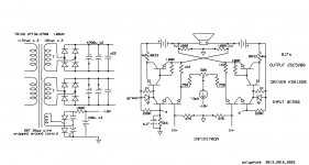
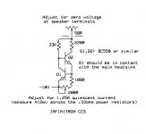
I have attached an updated schematic with more details for diy. Also attached is a separate schematic detailing the constant current source (CCS). This is a modification from the original, so the PCB is not quite up to date.
The PCB was a challenge (for me anyway) because of its density, as I had chosen a chassis that had limited space and had to make the PCB smaller than optimal.
Finally, I have a simulation using Paul Falstad's simulator, available at: http://www.falstad.com/circuit/
I could send you the code if you wish to try this.
Attachments
The A's join together.I am a little confused re the cascode connections marked A do these just join together or am I missing some thing
I am very keen to build this
Trev
@ Polyphaze
Much thanks for the updated schematic and the other details.
Surely the fact that you've been listening to the amp since its first build is worth a complimentary build from some of us, I think!
Not every one of us is a circuit geek, and many of us could benefit with a brief explanation of the circuit and its working/advantages etc. That is how, at least in my case, we learn stuff.
As for the PCB, your design could serve as a guide for other builders. So, kindly post yours. Now we have now excuse to wait further before ordering the parts and warming up the soldering iron!
Thanks and regards.
- Home
- Amplifiers
- Solid State
- I Call it INFINITRON