@ Polyphaze
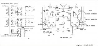
Before launching into the build, permit me to clear my doubts with you. In addition to the above queries, I have a few more. (Too bad the circuit diagram has no part numbers--not easy to refer to.)
Could you give a rough idea about the heatsink size?
Also, is it enough that the driver transistors have small heatsinks? (Do suggest a substitute for the KSA1220 devices.)
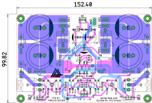
Kindly post your pcb layout design as it will serve as a guide for many of us.
As regards the input cascodes -- Is it enough that the two cascode pairs are matched closely, or has all the four to be matched?
Will the input pairs benefit from close thermal coupling?
Or, is it better to mount all the four cascode devices on a common slug of copper?
You have indicated Q1 of the CCS is to be mounted on the main heatsink. Will it be all right if both Q1 and Q2 of the CCS are mounted on the HS (mechanically easier to do that)?
What about the -10 V? If we are using a third winding of the transformer, has it to be regulated? Or is it enough that the voltage is roughly about -10 V? Can we use a 3-terminal regulator of 9 or 12 V that are readily available?
Is the amp stable with unbalanced input (for testing only)?
Thanks in advance.
Before launching into the build, permit me to clear my doubts with you. In addition to the above queries, I have a few more. (Too bad the circuit diagram has no part numbers--not easy to refer to.)
Could you give a rough idea about the heatsink size?
Also, is it enough that the driver transistors have small heatsinks? (Do suggest a substitute for the KSA1220 devices.)
Kindly post your pcb layout design as it will serve as a guide for many of us.
As regards the input cascodes -- Is it enough that the two cascode pairs are matched closely, or has all the four to be matched?
Will the input pairs benefit from close thermal coupling?
Or, is it better to mount all the four cascode devices on a common slug of copper?
You have indicated Q1 of the CCS is to be mounted on the main heatsink. Will it be all right if both Q1 and Q2 of the CCS are mounted on the HS (mechanically easier to do that)?
What about the -10 V? If we are using a third winding of the transformer, has it to be regulated? Or is it enough that the voltage is roughly about -10 V? Can we use a 3-terminal regulator of 9 or 12 V that are readily available?
Is the amp stable with unbalanced input (for testing only)?
Thanks in advance.
Hello..@ Polyphaze
Before launching into the build, permit me to clear my doubts with you. In addition to the above queries, I have a few more. (Too bad the circuit diagram has no part numbers--not easy to refer to.)
Could you give a rough idea about the heatsink size?
Also, is it enough that the driver transistors have small heatsinks? (Do suggest a substitute for the KSA1220 devices.)
Kindly post your pcb layout design as it will serve as a guide for many of us.
As regards the input cascodes -- Is it enough that the two cascode pairs are matched closely, or has all the four to be matched?
Will the input pairs benefit from close thermal coupling?
Or, is it better to mount all the four cascode devices on a common slug of copper?
You have indicated Q1 of the CCS is to be mounted on the main heatsink. Will it be all right if both Q1 and Q2 of the CCS are mounted on the HS (mechanically easier to do that)?
What about the -10 V? If we are using a third winding of the transformer, has it to be regulated? Or is it enough that the voltage is roughly about -10 V? Can we use a 3-terminal regulator of 9 or 12 V that are readily available?
Is the amp stable with unbalanced input (for testing only)?
Thanks in advance.
It appears that a KSA1142 is a good driver substitute and is more available. A small clip-on heatsink is fine.
Only the two input BJTs need to be matched. Close thermal coupling advised.
Only Q1 of the CSS should touch the heat sink. It doesn't have to be mounted.
-10V supply is not critical. Feel free to use a 9V battery initially.
Unbalanced input ok, best to connect a small (~500n) capacitor from -IN to gnd.
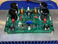
My remaining pcb documentation is of a format that does not upload here. I have attached a photo.
Finally, thanks for enhancing my schematic
Attachments
Yes, they are the 'usual' output inductors. I have no idea what they are for, but they are common in other designs, so I decided to include them.@ Polyphaze
I could see two inductors in the pcb pic. Are they the 'usual' output inductors?
Do we also need a Zobel network at the output? Is the amp stable without it for simple speaker loads?
Kindly clarify and guide.
I'm wondering now if I should remove them. What do you think?
I don't know what a Zobel network is, so I can't comment. But I have never experienced any stability issues.
They are in series with the speaker outputs. I'm not sure what they are for, but included them only because they are common in other amp designs.Thanks for the additional info Polyphaze. I’m also interested in building this amp. There are two inductors on your pcb but not in the schematic. Could you clarify their place in this circuit? Thank you.
Does the amp ring into a mildly capacitive load, 0.1uF to 1uF)?
If so, it needs the inductor(s) with a shunt small value resistor, although probably just one.
https://www.renardson-audio.com/damping.html
If so, it needs the inductor(s) with a shunt small value resistor, although probably just one.
https://www.renardson-audio.com/damping.html
Last edited:
Does the amp ring into a mildly capacitive load, 0.1uF to 1uF)?
If so, it needs the inductor(s) with a shunt small value resistor, although probably just one.
https://www.renardson-audio.com/damping.html
@ Polyphaze
While driving speakers with high capacitance and inductance values (blame the complex crossover networks!) amplifiers could exhibit instabilities, and the output inductor (often in parallel with a small damping resistor) is supposed to cure that tendency. I am no trained engineer-- this is what I have garnered from my reading.
The Zobel network is a series R-C network 'usually' tacked onto the output of solid state amplifiers, to make the complex speaker load appear to be resistive.
In amplifiers with rock solid stability (and if your speakers are simple and efficient as it is likely to be if you are driving them with low power class A amplifiers), these could be dispensed with. At least that is what is advised by Juma, a designer whom I respect much, elsewhere in the forum.
For those without a 'scope, chasing instabilities and HF oscillations is an uphill task. What I do often is, to wire up a Zobel network across the speaker output, and keep a finger on the R -- if the resistor overheats in a trice, you have oscillations for sure. Otherwise you could remove the Zobel and get on with listening to the amp... or rather, the music!
")
While driving speakers with high capacitance and inductance values (blame the complex crossover networks!) amplifiers could exhibit instabilities, and the output inductor (often in parallel with a small damping resistor) is supposed to cure that tendency. I am no trained engineer-- this is what I have garnered from my reading.
The Zobel network is a series R-C network 'usually' tacked onto the output of solid state amplifiers, to make the complex speaker load appear to be resistive.
In amplifiers with rock solid stability (and if your speakers are simple and efficient as it is likely to be if you are driving them with low power class A amplifiers), these could be dispensed with. At least that is what is advised by Juma, a designer whom I respect much, elsewhere in the forum.
For those without a 'scope, chasing instabilities and HF oscillations is an uphill task. What I do often is, to wire up a Zobel network across the speaker output, and keep a finger on the R -- if the resistor overheats in a trice, you have oscillations for sure. Otherwise you could remove the Zobel and get on with listening to the amp... or rather, the music!
Does the amp ring into a mildly capacitive load, 0.1uF to 1uF)?
If so, it needs the inductor(s) with a shunt small value resistor, although probably just one.
https://www.renardson-audio.com/damping.html
Got it. The inductors stay.@ Polyphaze
While driving speakers with high capacitance and inductance values (blame the complex crossover networks!) amplifiers could exhibit instabilities, and the output inductor (often in parallel with a small damping resistor) is supposed to cure that tendency. I am no trained engineer-- this is what I have garnered from my reading.
The Zobel network is a series R-C network 'usually' tacked onto the output of solid state amplifiers, to make the complex speaker load appear to be resistive.
In amplifiers with rock solid stability (and if your speakers are simple and efficient as it is likely to be if you are driving them with low power class A amplifiers), these could be dispensed with. At least that is what is advised by Juma, a designer whom I respect much, elsewhere in the forum.
For those without a 'scope, chasing instabilities and HF oscillations is an uphill task. What I do often is, to wire up a Zobel network across the speaker output, and keep a finger on the R -- if the resistor overheats in a trice, you have oscillations for sure. Otherwise you could remove the Zobel and get on with listening to the amp... or rather, the music!
Just a low level square wave at 10kHz with a nominal 8R load.
Look for ringing across the speaker outputs, before the inductors at low power.
Or sweep the response from 5kHz to 100kHz with a sine at low power.
You'll need a differential probe, or use the scope's A-B function.
Look for ringing across the speaker outputs, before the inductors at low power.
Or sweep the response from 5kHz to 100kHz with a sine at low power.
You'll need a differential probe, or use the scope's A-B function.
Last edited:
@ Vunce
I heard from Polyphaze that you have completed your Infinitron build.
Great news indeed!
Do share the details so that those of us who are planning a build will have more helpful information and tips. I have not been able to obtain the driver device, and so am looking for a good alternative. Looking forward to your posts.
Thanks and regards.
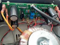
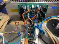
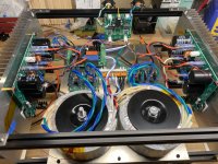
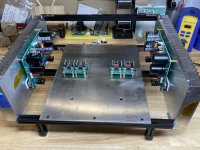
The Infinitron journey has been a great one. With input from posting members, the help from Polyphaze and Prasi a pcb was created to build an excellent sounding Infinitron amplifier.
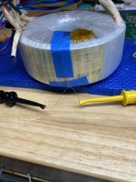
A pair of Antek AS-2218 transformers feed LT4320 active rectifiers for 24VDC. Bias current is limited to 1A because of heatsink size. I used Polyphaze’s method for CCS power by wrapping the transformers with 26awg enameled wire to create a separate winding for a few AC volts. After the heatsinks reach temperature equilibrium, the amp is very stable with +/-3mV DC offset.
Infinitron is fed a balanced signal from an SE/Bal converter (BTSB).
@The Prof, drivers are KSA1220Y in my amp but, Polyphaze has suggested KSA1142 as an alternative.
Like always, Prasi created a wonderful pcb layout to work with, thank you!
This amp has been a workhorse for the past month logging many, many hours. I am very happy with how this amp turned out, Polyphaze has a real “keeper” here that has been flying under the radar for almost 10 years. Its a bit late, Thanks for sharing Infinitron, Polyphaze!
(If there is interest, I can share the Gerbers)
Attachments
-
 BA3E44EC-7E9F-4622-B0AC-54AD4616772F.jpeg542.5 KB · Views: 231
 -
 42884C78-7546-49FE-A6E3-44A0854398D6.jpeg615.3 KB · Views: 145
 -
 4BEE7ACE-A327-4A6A-B120-A55FE4D655CE.jpeg574.2 KB · Views: 149
 -
 10D6353A-E9A3-4333-A7FA-DB3BCF3AE780.jpeg603.2 KB · Views: 170
 -
 infinitron-lay.png73.7 KB · Views: 238
 -
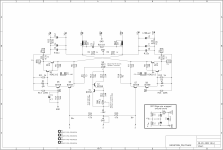 INFINITRON_SCH.png455.6 KB · Views: 245
- Home
- Amplifiers
- Solid State
- I Call it INFINITRON