Member
Joined 2009
Paid Member
Bigun, Nice looking speaker and nice looking bench supplies
he he he - amazing what you can find in the e-waste and fix
The speaker is new, I'm trying out the latest entry level driver from Mark Audio, see here: http://www.diyaudio.com/forums/full-range/138195-my-moon-onken.html
Well after exhaustive measurements and testing, I can't get my second board fixed : (
One thing I might do in the interim is just use the good board in a mono setup.
How should I wire the rca inputs and speaker outputs?
Is it ok to take the L and R signal from the preamp into the input on the TGM8 board - will that sum the left and right audio signal into a mono signal, or is it smarter to mix it in some other way?
For the outputs, I'm just going to put a link between the L and R speaker jacks so that I can get the mono signal coming out of both speakers - assuming driving two speakers isn't beyond the capabilities of a single TGM8 board?
Member
Joined 2009
Paid Member
That's annoying - so - First thing is to get the 2nd board in the post to Ranchu32 for some fix-ups (if his offer is still open - if not you can send it to me - send me a PM if interested)
To play in mono, for now, I would just pick the L or the R and use that. And I'd use just one speaker and listen to that. I listen mainly in mono and use just one speaker. Point the speaker across the room and allow the sound to bounce off the walls.
If you want to use two speakers then you can drive them both from one channel by wiring them in parallel or series. Wiring them in series will place less current demands on the amplifier and power supply. Seeing as this is likely to be a temporary solution I wouldn't worry too much about it but do watch the temperature of the amplifier if you go with parallel wired speakers and then driving them hard as this will be the more difficult load to drive.
If you want to mix the L and R at the input you could try to feed them through resistors to the input of the amplifier so that the amplifier input behaves like a summing point. It's probably not ideal though.
Last edited:
Ah you're quite right AndrewT. I followed Bigun's original circuit (CFP output) a little too closely and put the zobel on the wrong pins...
Does this look better?
When powering the amp the necessary current to charge C3 has to be supplied by the input transistor, that s why on some old designs of this kind a resistance in serial with Q1 collector is added, it wont change the caracteristics at all and will protect this transistor, i had this transistor failing on such a Motorola design that was popular 40 years ago, 1k-2k should be high enough to limit said charging current to safe values.
Member
Joined 2009
Paid Member
When powering the amp the necessary current to charge C3 has to be supplied by the input transistor.
According to a power start-up simulation the majority of the current to charge the feedback shunt capacitor comes from the output of the amplifier through the series feedback resistor and a smaller amount from the input transistor.
Member
Joined 2009
Paid Member
It's still the best sounding SS amplifier I've heard to date

Member
Joined 2009
Paid Member
Member
Joined 2009
Paid Member
And single Voltage supply with output Electrolytic.
And I remember that you were interested in this, single supply version of TGM8. Are you still interested ?
Bigun, I like the idea of an AC coupled TGM8 with on board power supply and output coupling cap. The input biasing scheme could be simplified (simple voltage divider perhaps?) since bias stability would no longer be much of a concern.
It might also be interesting to "spend" that transistor to create a compound pair VAS, with the extra gain judiciously applied for local and global feedback.
Keen to collaborate if either of you decide to pick up this project.
It might also be interesting to "spend" that transistor to create a compound pair VAS, with the extra gain judiciously applied for local and global feedback.
Keen to collaborate if either of you decide to pick up this project.
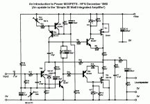
I thought this was an interesting circuit, it reminds me of the TGM8. We have a Singleton input stage and a CFP output.
Yes, JLH designed some interesting circuits in his time.
Dear Bigun and Ranchu32,
Please see http://www.diyaudio.com/forums/solid-state/250380-biguns-tgm8-single-supply-2.html. I continued the posting there.
--gannaji.
Please see http://www.diyaudio.com/forums/solid-state/250380-biguns-tgm8-single-supply-2.html. I continued the posting there.
--gannaji.
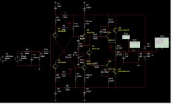
Hi everyone, Bigun, very interesting your circuit, I am in need of an amp DIY good quality, first I would do the P3A, but you came up with this variant, and soon after I saw the vssa, so I decided to do vssa, but it is so difficult to find Mosfets, so I started to move in tgm8 in SPICE, I wanted to make them a "symmetrical" (without bootstrip) when I finished I had a new variant or rather a fusion: P3A + tgm8 + vssa? I could put the scheme here, for you to tell me if it works correctly what do you think?
- Home
- Amplifiers
- Solid State
- TGM8 - my best amplifier, incredible bass, clear highs, no fatigue (inspired by Rod Elliot P3a)

