Thanks Gareth and Hugh, it seems the idea has some merit and is worth pursuing.
If you Google "double bootstrap VAS" the link above is the first result after a few DIYAUDIO threads.
DIY 40W MOSFET AMP
There doesn't seem to be many designs with this arrangement. Mind you there aren't so many designs that still use a bootstrap CCS, fewer still with a bootstrap and MOSFET output stage.
Hugh, thanks for your description of the bias generator and suggested parts values. To be honest I still don't fully understand how to design this functional block and I probably need to invest further time to study it.
The bias generator R values in the schematic above were taken directly from the International Rectifier app. note I referenced. Mind you the HEXFETs used in that design are different, so its no surprise to learn that these values when used in this circuit are grossly inadequate, assuming of course that the app. note design was optimal in the first place, which I wouldn't assume.
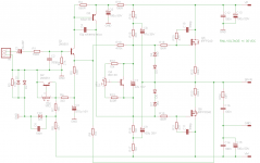
The earlier sch (497) and the latest sch (503) both have 240 & 9240 as the outputs.
But in both sch the 9240 is drawn upside down with the Source connected to the supply rail.
But the integral Zener is the correct orientation ??????
Or should that be a diode.
It's the Gate to Source that sometimes have a Zener.
But in both sch the 9240 is drawn upside down with the Source connected to the supply rail.
But the integral Zener is the correct orientation ??????
Or should that be a diode.
It's the Gate to Source that sometimes have a Zener.
Last edited:
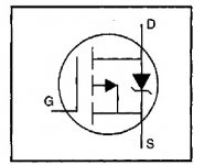
this is drawn correctly.I thing P channel Q6 drawn correctly.
This is not what is drawn in the two schematics.
I'm having a little trouble obtaining the correct voltages from the rectifier for my TGM8. I am aiming for a 35v supply, but only have a toroidal transformer with dual 25v secondaries.
The outputs of the toroid are (red,black) and (white,orange). So i tied the black/white wires together and then to ground in order to create a centre tap. The issue is that the AC I read across red-orange is ~50v, which is then giving post-rectified 70v DC.
I've also tried swapping the wires used as a centre tap, but that doesn't get the required 35v dac either. Any pointers?
Hello
At Plitron transformers but mostly other transformers to the wires at the secondary Red, Grey, Blue, Yellow ----Blue and Yellow for center tap for ground!Now you have to measure the + or - Voltage Red to center tap or Grey to center tap.Between red and Grey you get 2X as high Voltage.
Primary if it has dual 120V-120V Brown-Black-Orange-White the wire colors
You can connect them several ways, pay to that to.
If it has only single primary that is easy if the transformer has the right primary Voltage (120V or 230V depend at your country residential Voltage.
That must be match on your primary otherwise you get wrong Voltage and VA rating on the Sec.
Also if you measure the voltage after the bridge usually you get a couple V higher without load if everything connected well but not like you in these case
You should get around 36V-0-36VDC out of 25VAC if everything connected rightly!!
Greetings
Last edited:
Ok so instead of measuring from + to - on the rectifier, I should measure from + to GND and then GND to -?
exactly
Hi lordearl
It sounds like you have wired up your transformer and bridge rectifier perfectly. When you joined the black and white transformer secondary wires together, you effectively added a "centre tap" to your dual secondaries transformer. Put a lug on the end of these wires because this centre tap is your 0V reference and the basis for the star ground.
If you put the positive probe on the +ve rectifier output and negative probe on the centre tap you should read approx. 35VDC. Move the positive probe to your -ve rectifier lug and it should change to approx. -35VDC.
If you haven't got any filter caps connected yet then the voltages will be a little off due to the gross voltage ripple.
Let us know if you need more help wiring up the rest of the power supply.
Ok great, thought I'd better check the PSU voltages prior to connecting the amplifier modules....better to be safe.
Only thing remaining is to wire up the LED for the power on button. I was planning to just steal the voltage from the + and - of the rectifier. Given there's about 70v there, would a resistor of 2k8 or so get it down to the 12v required for the LED?
Only thing remaining is to wire up the LED for the power on button. I was planning to just steal the voltage from the + and - of the rectifier. Given there's about 70v there, would a resistor of 2k8 or so get it down to the 12v required for the LED?
- Home
- Amplifiers
- Solid State
- TGM8 - my best amplifier, incredible bass, clear highs, no fatigue (inspired by Rod Elliot P3a)