Member
Joined 2009
Paid Member
The LED will create it's own voltage drop (it'll behave like a constant voltage generator) so just calculate for a suitable current. Since the diode voltage drop is small compared with the rail voltage, just use the rail voltage in your calculation: R = voltage / current. The 'original' red LED's were often used at around 10mA so you'd want R=35V/10mA=3k6 resistor. But modern LED's can be too bright at such currents. I've used LED's at only 1mA (and even less for a HT amplifier to be used in a dark room) which would need a 36K resistor. The exact value is unimportant, try different values in this range to get the brightness you want. A small low power resistor will be fine (P=10mA x 35V = 350mW so 1/2W for 10mA and 1/6W is enough for 1mA). Some modern LED's will not tolerate large reverse voltages so be careful to connect the LED the right way around.
Another TGM8 lives...well sort of!
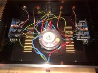
Thanks to all your help, we finally have lift off with Australia's 2nd (AFAIK) TGM8.
After finishing the wiring (see pic), I powered it up and monitored the current draw on idle, 0.1A, which was fine. Tested on some old speakers, channel by channel, no concerns at all - we have music.
HOWEVER, on checking the DC offset, I noted one channel had negligible offset, whereas the other had 6.5v!
So (somewhat foolishly in hindsight) I used the trimmer to reduce the offset, but as I turned it to about the 3v mark, I heard a loud pop which sounded remarkably like an LED exploding. Sure enough, the LED on the board appears to have failed.
I also noticed (independently of the above set of events) that the LED on the functional board turns on only momentarily when I power up the amp. It's the only LED on the board, but I can't tell from the schematic what this LED does in the circuit. Should it be on permanently when the amp is powered on?
Any troubleshooting would be greatly appreciated, cheers.
Attachments
Member
Joined 2009
Paid Member
The LED is not a power indicator but instead it lights red if there is a dc error at the output. Otherwise, unless the edit described earlier in the thread was made to the pcb by Christian before he sent them to you, the LED's stay off. With the edit they light green when there is no dc error. It is also normal for them to light briefly on power up, this is the turn on delay stopping any turn on thumps in the speakers.
How does the good channel sound ?
As for the bad channel, I don't have a quick answer and will have to think about it. I'm on travel for a couple of days so it won't be easy... note that as described earlier in the thread, there is an error on the silk screen, the offset and bias pots are mislabelled. The bias pot is labelled offset. The offset pot is labelled bias. The pcb files I posted later on have this error fixed.
By the way, where is your safety earth, from the IEC power inlet connected ? to the chasis I hope!
Last edited:
Ok we can wait to hear from Christian if he implemented the green led function, but for now it sounds like the initial red flash followed by turning off is the way it should be operating. Which is fine as that confirms that the LED is blown in the bad channel - it doesn't flash when I turn the amp on.
As to the sound - phenomenal, incredibly relaxed, yet still highly detailed! Tempted to use the good channel on my better speakers just to enjoy it for a while! A very inviting sound for sure.
Yes, the safety earth is connected to all the other grounds (in the pic above with the big bolt and plenty of spades).
Oh and 3k9 2W was perfect for the power indicator LED, not too bright all ; )
Hi Bigun,
Any boards available for the TGM8?
I had the same question few page back

Hi Tom
Congratulations on getting one channel working, and don't worry, we work through any problems to ensure the second channel is fixed too.
But first of all, can you please drill a second hole in the chassis, so that the safety ground has its own dedicated attachment point right next to the IEC connector? AndrewT will go beserk if he sees it bolted to the star ground!
Make sure all paint around the hole has been scraped away then lay down a star washer, the earth lug, a flat washer and then TWO bolts on top so that there is no possibility it can come loose. Put your multimeter across the earth pin on the power plug and a bit of exposed metal on the case to make sure there is no resistance. This could save your life if there is no RCD in your meter box or it is faulty.
As Bigun said, the LED is a DC offset indicator not power indicator. The brief red flash before turning green is also normal; it means its catching the brief surge of DC on power up.
To be honest I don't know why one channel had huge DC offset. I tested and trimmed both boards before I sent them off for 0V offset and suitable bias. It might be easier to send the faulty board back to me to have a look at?
Thanks Christian. So on your board do the LEDs flash red then turn green?
On mine they flash red, then completely off.
Ok I'll put another hole next to the IEC, easy.
If we can't do some simple tests on the bad board over the next few days I'll send it your way for some expert treatment ; )
On mine they flash red, then completely off.
Ok I'll put another hole next to the IEC, easy.
If we can't do some simple tests on the bad board over the next few days I'll send it your way for some expert treatment ; )
Ok, yes, re-tested on both boards, the good one has only 0.13mV offset and the led flashes on momentarily, music plays fine. The bad board has no LED flash, and about 12V (!) offset and doesn't play music at all.
At least the LED is easily replaced (provided no other damage has been done).
At least the LED is easily replaced (provided no other damage has been done).
Ok, with respect to ground:
Good channel -
Q1; -0.731v, -108.1mV, 36.64v.
Q2; -6.07v, -5.4v, 25.2mV.
LED; 1.356v (red->centre as green is n/a)
Bad channel -
Q1; 17.51v (slowly keeps increasing), 17.31 (also increasing), 38.42v.
Q2; 18.8v (increasing), 18.9v (increasing), 19.2v (increasing).
LED; 1.178v (red->centre)
Good channel -
Q1; -0.731v, -108.1mV, 36.64v.
Q2; -6.07v, -5.4v, 25.2mV.
LED; 1.356v (red->centre as green is n/a)
Bad channel -
Q1; 17.51v (slowly keeps increasing), 17.31 (also increasing), 38.42v.
Q2; 18.8v (increasing), 18.9v (increasing), 19.2v (increasing).
LED; 1.178v (red->centre)
Member
Joined 2009
Paid Member
I had the same question few page back
I do have a few, probably enough for two pairs. Posted by regular letter air mail US20dollars the pair.
PM me.
Sorry Lordearl, difficult to help as I am on travel, in Hong Kong with phone only last week and now in UK with a borrowed iPad access only, will be back in Canada next week.
Last edited:
Member
Joined 2009
Paid Member
As to the sound - phenomenal, incredibly relaxed, yet still highly detailed! Tempted to use the good channel on my better speakers just to enjoy it for a while! A very inviting sound for sure.
Good to hear (now you understand why I have elected not to design any more solid state amplifiers, time is short and TGM8 is what I have been wanting to achieve in SS) - which doesn't mean to say that there aren't better amplifiers out there.
Last edited:
Member
Joined 2009
Paid Member
The bipolar are the outputs, operating in Class AB. The power FETS operate in Class C (normally off) and they slide in gently to help when more power is needed (either when you crank up the signal or if the load has impedance dips). This has the following benefits (in my opinion), a) retains great sound of single bipolar output pair at normal listening levels with 'normal' speaker loads, b) no parts to match, c) protects bipolar devices from beta-droop and high currents, d) limits Current draw from the drivers thus protecting them and hence a less demanding thermal control loop
I have yet to fully compare the TGM7 and TGM8. They are both superb sounding to my ears. TGM8 runs much cooler of course and has the convenience of built in speaker protection and power filter caps.
Soundwise I thought TGM7 would be unbeatable but much of the design was not mine. I set myself the one-time challenge of trying to beat it. The TGM8 might just do that, not only is the TGM8 bass strong and powerful but the mids and highs have more air, more nuance. I will use TGM7 for my HT and TGM8 for music duties. I'll be able to share more opinion once I've had more listening time.
Last edited:
- Home
- Amplifiers
- Solid State
- TGM8 - my best amplifier, incredible bass, clear highs, no fatigue (inspired by Rod Elliot P3a)