It really is very nice sounding. Seems as good as the VSSA and that is one fine sounding amp.
I must admit I was hating the smd's at first but I think it was mainly the difficulty with seeing the part numbers. Once I got the hang of soldering them in they aren't so bad. The biggest thing for me is stock. I have most all of the values of through hole resistors and film caps in my parts bin. SMD's, not so, though I do have a pretty good start on the SMD resistor collection now since the place I bought them from has a 50 piece minimum per value. I'm going to have to go back and read though the thread again so I can learn about the decision to use MOSFET with BJT in the outputs. I read this thread just a few posts at a time as I got email notices but was building other amps at the time. I want to learn what the advantages/disadvantages of this type of topology are.
Blessings, Terry
Member
Joined 2009
Paid Member
the decision to use MOSFET with BJT in the outputs
The main outputs are the BJTs. With typical speakers and at typical home listening levels it is the BJTs that are providing most of the music. I chose BJTs because a) I wanted to base the design on the proven P3a at first, b) they have high transconductance, c) I am more familiar with working with BJTs than FETs and feel that I know how to get the most out of them, d) but-BJT CFPs are more common and therefore, a little more 'proven', e) generally they can be biassed at lower idle currents
I wanted to provide the ability to source more current, either for difficult loads or to allow for more power. This is usually accomplished by adding more output pairs. But I didn't want to double up on the number of output devices because this is more complex with a CFP output, increases the standing idle current and requires device matching. The solution was to add a pair of additional outputs in Class C - they remain off and out of the way for most of the time. Idle current is not affected, device matching is not required.
The FETs kick-in only when the amplifier needs to provide more than an amp or so of current. This helps because a) FETs don't suffer from beta-droop and in this case they also prevent the main output BJT entering into beta-droop, b) FETs are a little more robust than the BJTs I used so are well positioned to deliver the higher current spikes, c) they don't require base current so they limit the current drive requirements for the drivers at very high output currents, thus also helping reduce temperature fluctuations in all the BJTs
Last edited:
Hi Gareth,
Very interesting. I actually used NJW0281/0302 for the outputs. Not sure if that affects you design. It's what I had that fit well. I have a large stock of Onsemi devices because of their samples program.
I'm going to study this thread some more because it is so different from the other amps I've built. It really amazes me how many different ways you can approach amplifier design and still get stellar performance.
Blessings, Terry
The big advantage of the CFP is that the temperature of output devices do not significantly affect the crossover distortion of the stage.
The drivers do most of the setting of the bias requirement and the drivers do not vary in temperature that much.
If the drivers have a decent heatsink and have an appropriate bias current then you will find that crossover distortion does not vary much as the output pair change in temperature due to load currents.
The CFP is quite different from an EF stage in this respect.
In fact, of all output stages CFP is the most suitable for pure class B operation (zero biasing of output transistors), in spite of the zero crossing signature. Optimal bias is only for the people that require lab performance to be as good as possible.
Hi Bigun
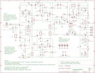
I am having difficulties understanding your capacitor orientation on the feedback line.
while idling you should have around -0.9V om the node joining R5 (56r), R12 (4k7r) and C3 (470u).
So this cap sees a negative voltage on top and is connected to GND on the other side.... Why did you connect it's minus leg to GND ?
Is it because of the action of R3 (10r) connected to GND ?
Attachments
Member
Joined 2009
Paid Member
Great question, nobody noticed, including the designer - I've just looked at how I built my own modules and indeed I did orient the cap so that the negative terminal is to the ground plane as on the schematic. But you are right, they should be the other way around. I guess such a small voltage is not a problem but I don't know if there's a long term reliability issue. Just in case, I am going to desolder my C3 and turn it around !
R5 will pass audio current while not quiescent.
This means the voltage on C3 will be modulated and thus vary either side of the quiescent value.
-0.9Vdc will probably not harm the electrolytic, but this is uncomfortably close to the -ve limits I have seen quoted (varies from -1V to -1.4V of -ve bias as maximum).
Audio modulation may take the electro significantly outside normal -ve bias limit.
Measuring the electrolytic bias voltage is wise for all builds. This would have caught the error sooner.
This is important when DC blocking capacitors are used in conventional LTP input amplifiers and opamps. The choice of PNP or NPN for LTP reverses the capacitor bias.
Member
Joined 2009
Paid Member
I think a bipolar cap for C3 would be a good choice too.
What surprised me about bipolar caps was using one on the input sounded good. Rather than use a film cap a small bipolar looks to me, to be a valid option.
I think the majority of gurus still prefer large film caps though and they may be right.
Some interesting comments here too: Capacitor Distortion Part 2
Member
Joined 2009
Paid Member
It does sound good with loads of detail and quite powerfull bass but I feel the high frequencies are not on par with the rest.
I see you started with a BD140 for VAS with Cdom 47p
Then you changed the design using a two pole compensation, still using the BD140 but included an emitter follower in the miller loop. In this case you lowered the miller Cdom to 22p.
I am using your initial approach with a BD140 and 47p Cdom and my simulations showed compression on the current on the input transistor collector.
Allready have agreement that I can lower Cdom to 10p without compromising stability and sim shows nice spikes on input collector current when fed with 1v 20Khz squares.
Now I would like to try a lower Cob transistor for the VAS (KSA1381) and I see that you posted that option but with a Cdom of 68p....... can I lower this value to 10p without fear ?
Member
Joined 2009
Paid Member
If I read and understood your post correctly - you are building the amplifier with the simpler 2-device input stage and single-pole Cdom compensation. Based on that I'd offer the following:
I have not built the version with single pole front end, only two pole. So my Cdom recommendations for single pole are based only on simulation. I know from experience that with single pole compensation you have to tune Cdom by ear. Too high and the amplifier sounds sluggish, too low and it can sound shrill, and just right - is just right")
If you are looking for a brighter sound up top (just an assumption) then try 33pF Cdom with single pole and vary either side. Will 10pF be safe ? - maybe borderline, you'd have to look carefully with a signal generator, an o'scope and a load with a little capacitance to simulate a speaker cable.
I did use the KSA part. I like the KSA part, it has very good performance on-paper and I've retroffited a similar part to my TGM1 amplifier to good effect.
Interesting comments on the treble. I think you are on the right track to explore the Cdom question to 'voice' the amplifier for your speakers and ears. At the same time, I would encourage you to build the full version of TGM8 with the 3-transistor input stage and two-pole compensation (if you haven't done that yet).
I have not built the version with single pole front end, only two pole. So my Cdom recommendations for single pole are based only on simulation. I know from experience that with single pole compensation you have to tune Cdom by ear. Too high and the amplifier sounds sluggish, too low and it can sound shrill, and just right - is just right
If you are looking for a brighter sound up top (just an assumption) then try 33pF Cdom with single pole and vary either side. Will 10pF be safe ? - maybe borderline, you'd have to look carefully with a signal generator, an o'scope and a load with a little capacitance to simulate a speaker cable.
I did use the KSA part. I like the KSA part, it has very good performance on-paper and I've retroffited a similar part to my TGM1 amplifier to good effect.
Interesting comments on the treble. I think you are on the right track to explore the Cdom question to 'voice' the amplifier for your speakers and ears. At the same time, I would encourage you to build the full version of TGM8 with the 3-transistor input stage and two-pole compensation (if you haven't done that yet).
Thank you for your prompt answer.
In reality I am using your input stage and single pole/transistor VAS.
With 47p Cdom, it sounds incredibly good in the bass but the trebble lacks the subliminar micro detail I am used from other amps, so in the end I get the impression of harshness and lack of spatiality.
I believe that is the signature of compression due to the fact the input transistor not beeing able to charge/discharge Cdom as fast as it should.... That is why I believe reducing this cap would help.
I am quite sure it will be stable with 10p and the BD140 for the VAS, but if I use the KSA (with much lower Cob) I am not sure I can use such a low Cdom.
Using a signal generator and a scope, what should I look for ? should I input 20k squares and look for spikes on the output ?
How can I predict instability with this Equipment ?
Member
Joined 2009
Paid Member
The tel-tale sign of instability I look for is just as you say, input a square wave and see if the rising/falling edges ring and bounce around. I little bit of overshoot is OK. But be careful, driving the amplifier with 20kHz square waves can over-heat it. Ultimately, you are using square waves because they have fast rising/falling edges - so I'm not convinced that you need 20kHz square waves. I generally use 1kHz square waves because my o'scope has a scope-probe calibration point on the front which generates a very good clean and super-fast square wave at 1kHz that beats anything my signal generator can produce.
I'm not experienced or expert enough to comment on the treble you hear. But I do know my TGM8 has better treble than my other amplifiers. Mind you, my ears don't work much above 15kHz these days. Also, the two-pole compensation provides more OLG and hence lower distortion for high frequencies than the single pole compensation. I'm using a bipolar input cap and you are using a film cap - could this have some impact too.
I'm not experienced or expert enough to comment on the treble you hear. But I do know my TGM8 has better treble than my other amplifiers. Mind you, my ears don't work much above 15kHz these days. Also, the two-pole compensation provides more OLG and hence lower distortion for high frequencies than the single pole compensation. I'm using a bipolar input cap and you are using a film cap - could this have some impact too.
Last edited:
Member
Joined 2009
Paid Member
I have not measured the current but I would trust LTSpice to give a value close enough to reality for your purpose. You can increase the current through the input transistor with this change but I'm not sure you want to push it too far in terms of thermal dissipation - depends on your voltage rails of course but 11 mA is pretty high. In addition, you should check the dc-offset circuit, it may also need some resistor values to be changed in order to keep the dc-offset adjustment in-range.
fyi - My TGM2 used a CFP input to allow more current to drive Cdom and improve slew rate. The treble was too harsh for my liking on that design though.
fyi - My TGM2 used a CFP input to allow more current to drive Cdom and improve slew rate. The treble was too harsh for my liking on that design though.
- Home
- Amplifiers
- Solid State
- TGM8 - my best amplifier, incredible bass, clear highs, no fatigue (inspired by Rod Elliot P3a)