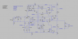
Very nice!Thanks for suggestions. I have modified the layout as advised. Revised layout attached.
Don't know what rails voltage you gonna use, but for higher voltage/power, you'll need heatsinks on VAS transistors (Q5/Q6), and drivers as well.
Over 35V rails, they can run pretty hot...
As a longtime happy listener of circlophone, i wish to state that it gets even better with a tube buffer. Details in this thread.
12 volt ECC82 0dB hybrid class AA headphone/ preamplifier
Thanks Again Mr. Elvee, for your circlophone is my major source of musical bliss during these lockdown days.
12 volt ECC82 0dB hybrid class AA headphone/ preamplifier
Thanks Again Mr. Elvee, for your circlophone is my major source of musical bliss during these lockdown days.
Last edited:
Final modified layout of Circlophone based on Mr project16 layout. PDF is 200% of actual size. I intend to build Circlophone on this PCB Layout. Thanks Mr Elvee and Mr project16.
Attachments
Low voltage adapted for headphone use
Hi Elvee,
I built a headphone adapter for the low voltage bonsai version. The headphone and external speakers can be switched by a toggle. I used the voltage divider scheme to provide a max of 36mW for a 32 Ohm headphone.
I tested it with an old Denon AH-D210 I had lying around and it sounds really good.
Thanks!
Attachments
Well, it is an unexpected development, and to be honest, I find it a bit too complex for a headphone-only amp, but why not, and it certainly gives good results.
For headphones, I would rather favor a class-A PP in the xyz-style (the name of the creator escapes me for now, but I used it in the driver section of this project: Volume control, Evil Mad Scientist style).
It is much simpler, uses a comparable amount of of power and offers an excellent quality too.
If someone can recognize the xyz topology, i would be grateful if he/she can name it, otherwise i am going to lose sleep about it until my memories come back
It looks perfectly OK then.
About the headphones divider, I am not sure that it is the best solution for all types of HP: traditionally, headphones were connected to the main amplifier output via a single, largish resistor (470 ohm or 1K for example).
This was more or less equivalent to current drive, and for many types it resulted in a pleasant sound.
Nowadays, many audio devices have a HP output only, and the impedance is very low, resulting in a high damping factor.
Those types are probably optimized for such a driving method.
With your divider, you have a tradeoff between the two methods: a more or less matched drive, similar to many tube amps.
It may be the best option for your HP's
Hi,
Is this a tested Layout?
Wish to make a pcb by toner transfer and assemble the amp.
Thanks and regards,
Sumesh
Is this a tested Layout?
Wish to make a pcb by toner transfer and assemble the amp.
Thanks and regards,
Sumesh
Final modified layout of Circlophone based on Mr project16 layout. PDF is 200% of actual size. I intend to build Circlophone on this PCB Layout. Thanks Mr Elvee and Mr project16.
Well, it is an unexpected development, and to be honest, I find it a bit too complex for a headphone-only amp, but why not, and it certainly gives good results.
For headphones, I would rather favor a class-A PP in the xyz-style (the name of the creator escapes me for now, but I used it in the driver section of this project: Volume control, Evil Mad Scientist style).
It is much simpler, uses a comparable amount of of power and offers an excellent quality too.
If someone can recognize the xyz topology, i would be grateful if he/she can name it, otherwise i am going to lose sleep about it until my memories come back
Hi Elvee,
I came across this circuit which seemed similar to the one you used in your volume control.
Headphone Amplifier - RED - Page30
That' s too much: I cannot stand it any longer, I am going to open a thread dedicated to that topology.
Someone from DIYaudio or elsewhere must have the answer
The circuit in the link given in post 490 has much in common with a design by Linsley-Hood - part of a modular preamplifier project.
I have a separate listening space now and don't listen through phones any more but this module was pleasing to listen through.
Attachments
Helpful members relieved my suffering: Anybody remembers the name of this OP stage?
It is an Allison topology.
But your suggestion is undoubtedly an excellent one for head-amp, which was the sub-subject of this discussion.
It is an Allison topology.
But your suggestion is undoubtedly an excellent one for head-amp, which was the sub-subject of this discussion.
Hi all,
This thread has been a safe harbor for me during the last 6 months of global craziness.
Sincere thanks to Elvee, Daniel, et al.
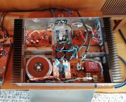
I built the 'Standard' Circlophone on page one ( 35vdc ) on diy wakibaki pcbs. My second amp build.
It is wonderful... Clean, lean music making machine. Pleasant mix of musicality and precision at all frequency ranges. Perfect scope measurements.
I have two questions:
Is there any reason not to use a nonpolar / bipolar feedback capacitor (C3)?
Is a lower voltage supply preferable when driving low impedance loads?
This thread has been a safe harbor for me during the last 6 months of global craziness.
Sincere thanks to Elvee, Daniel, et al.
I built the 'Standard' Circlophone on page one ( 35vdc ) on diy wakibaki pcbs. My second amp build.
It is wonderful... Clean, lean music making machine. Pleasant mix of musicality and precision at all frequency ranges. Perfect scope measurements.
I have two questions:
Is there any reason not to use a nonpolar / bipolar feedback capacitor (C3)?
Is a lower voltage supply preferable when driving low impedance loads?
Attachments
Welcome to the C-club!Pleasant mix of musicality and precision at all frequency ranges. Perfect scope measurements.
You can always use a BP cap in all polar caps roles, and C3 is no exception.Is there any reason not to use a nonpolar / bipolar feedback capacitor (C3)?
BP caps are bulkier and more expensive than regular, polar caps, and when they are not needed they are normally dispensed with, but you are perfectly free to use one in this case.
In the case of C3, it will normally see the polarity indicated on the schematic. It's only mV's, meaning you could safely install it the wrong way (but I don't recommend it!), and if something goes really wrong (with the output stuck to a rail for example), the back-to-back diodes will protect it.
To summarize: using a BP cap is not needed and brings no benefit, but it cannot harm anything either.
It all depends on the max output power you need: P=U²/R, which means that a lower impedance will increase the power accordingly, maybe exceeding the limit of your speaker or your circlophone build if you keep the same supply voltage.Is a lower voltage supply preferable when driving low impedance loads?
The C is like any other amplifier, and the output power is dependent on the supply voltage and the load impedance: its peak output voltage is the rail voltage minus 1.5V. From there you can derive the rms output voltage and the output power.
The subject is well covered on the net and DIYaudio, but if you need more details you can always ask.
You should avoid designing an amplifier having a larger output capability than your target speaker: there is always the risk of someone pushing the volume knob to the max and frying your speakers
Q12 and Q13 transistors
Undertaking mega project of building Linkwitz LX521 inspired speakers with full 4 way active crossover and 10 power amplifiers.
All 10 amps will be circlophone with identical power supply of +- 35V DC (from 25-0-25 trafo )
I already have board built for ECB type transistor for Q12 and Q13 with KSC1845 in mind, but unfortunately these are out of stock with major genuine retailers , planning to substitute with KSC23830TA.
As per Elvee's earlier instruction, these should work fine on 35V rail. Still want to get members opinion( Hate to do repair and part replacement) .
- Home
- Amplifiers
- Solid State
- Building Elvee's Circlophone: Documentation, Parts, Accessories, & beginner friendly